
Connector

A connector and male connector technology, applied in the direction of connection, connecting device parts, contact parts, etc., can solve structural strength, sealing electromagnetic shielding performance defects, battery charging takes a long time, poor contact surface stability, etc. problem, to achieve stable contact area, improve sealing and waterproof performance, and good electromagnetic shielding performance

Active Publication Date: 2013-05-15
FUTURE TECH JIANGXI
View PDF7 Cites 19 Cited by
  • Summary
  • Abstract
  • Description
  • Claims
  • Application Information

AI Technical Summary

Problems solved by technology

Due to the small contact area of ​​the existing connector terminals during docking, the stability of the contact surface is relatively poor, so that the existing connector can only pass a small current of 0.5A-2.0A, the charging speed is slow, and the battery charging takes a long time
In addition, the metal shell of the connector is formed by stamping and bending with a mold, and the metal shell and the rubber core are fixed and assembled through clamping points, which has defects in structural strength, sealing and electromagnetic shielding performance; during use, due to the With fool-proof design, it can only be plugged in one direction, which is inconvenient to use

Method used


Image

  • Connector
  • Connector
  • Connector

Examples


Embodiment Construction

[0023] It should be noted that, in the case of no conflict, the embodiments in the present application and the technical features in the embodiments can be combined with each other. The present application will be further described in detail below in conjunction with the drawings and specific embodiments.

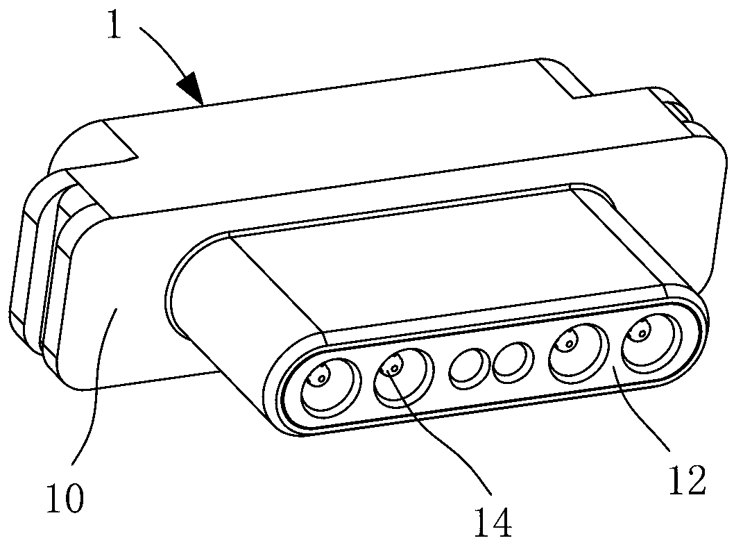
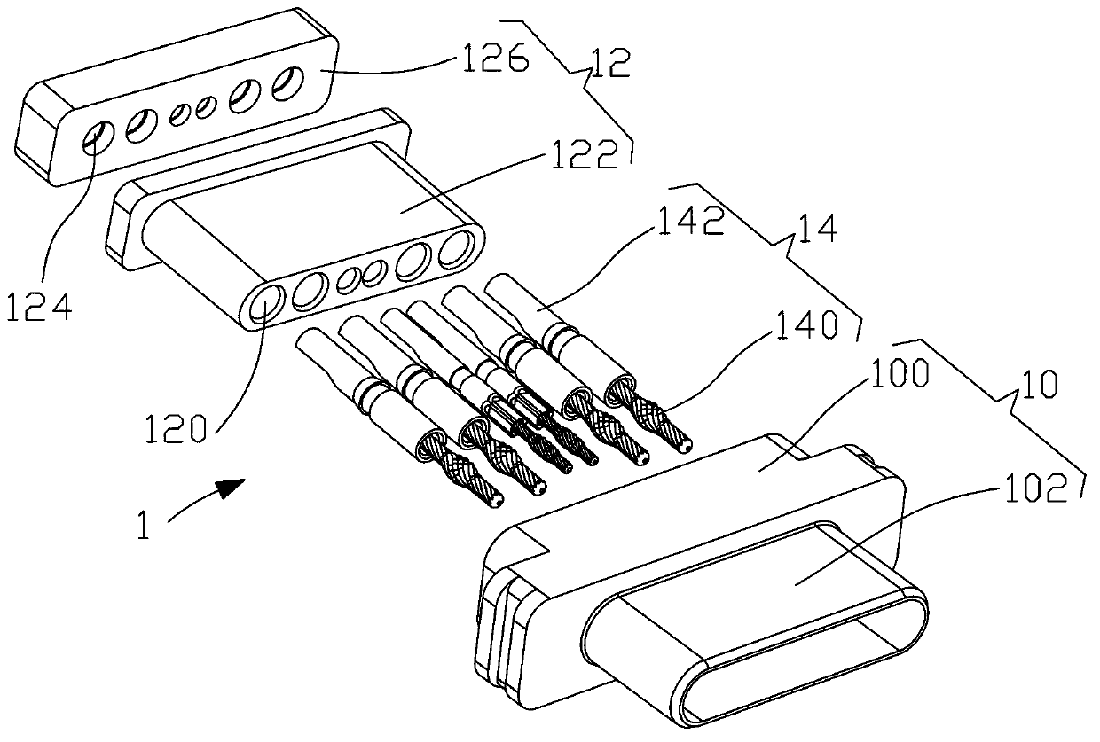
[0024] Such as Figure 1~Figure 6 As shown, the present invention provides a connector, including a male connector 1 and a female connector 2 that are inserted into each other.

[0025] Such as figure 1 and figure 2 As shown, the male connector 1 includes a male metal shell 10 , a male rubber core 12 assembled inside the male metal shell 10 , and a male terminal 14 assembled on the male rubber core 12 . The male metal shell 10 is formed by cutting a metal blank. The male metal shell 10 includes a male main body 100 and a plug shell 102 integrally protruding from the front end of the male main body 100. The male rubber The core 12 and the front ends of the male terminals...


PUM


Abstract

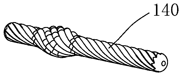
The invention relates to a connector which comprises a male connector and a female connector which are mutually connected in an insertion mode. The male connector comprises a male terminal which is composed of an inserted connection part and a welding line part riveted at the back end of the inserted connection part. The inserted connection part is formed by twisting a plurality of metal wires. The female connector comprises a female terminal made of a copper tube. The inserted connection part is formed by twisting the plurality of metal wires and then is integrated with the welding line part in a riveted mode, and the female terminal is made of the copper tube, and therefore large currents can be transmitted at butt joint time of the male connector and the female connector. Tests prove that each terminal can bear 5A currents, and terminals for detection also can bear 3A currents. The connector can meet requirements of quick charging a battery of high power capacity.

Description

technical field [0001] The invention relates to the technical field of connectors. Background technique [0002] There are mainly two forming methods for terminals of existing connectors: forming by punching and bending a thin metal sheet or cutting and forming by a single metal wire. Due to the small contact area of ​​the existing connector terminals during docking, the stability of the contact surface is relatively poor, so that the existing connector can only pass a small current of 0.5A-2.0A, the charging speed is slow, and the battery charging It takes a long time. In addition, the metal shell of the connector is formed by stamping and bending with a mold, and the metal shell and the rubber core are fixed and assembled through clamping points, which has defects in structural strength, sealing and electromagnetic shielding performance; during use, due to the With fool-proof design, it can only be plugged in one direction, which is inconvenient to use. Contents of the...

Claims


Application Information

Patent Timeline
IPC IPC(8): H01R13/04H01R13/10H01R13/516H01R13/52
Inventor 池金平
Owner FUTURE TECH JIANGXI
Learn More