Eureka AIR delivers breakthrough ideas for toughest innovation challenges, trusted by R&D personnel around the world.

Multifunctional signal transformation network bridge

A signal conversion and multi-functional technology, applied in the direction of electrical components, transmission systems, etc., can solve the problems of incompatibility with bus protocols, etc., and achieve the effect of simple wiring, convenient operation and conversion, and compact structure

Inactive Publication Date: 2013-05-15
SNTO TECH GRP
View PDF3 Cites 3 Cited by
  • Summary
  • Abstract
  • Description
  • Claims
  • Application Information

AI Technical Summary

Problems solved by technology

The Philips I 2 The C protocol is a bus that uses the least signal lines among various buses and has strong functions such as automatic addressing, multi-master clock synchronization and arbitration. Therefore, using I 2 The control system designed by C is very convenient, flexible, and small in size, and has been widely used in various practical applications, but it is not compatible with other bus protocols mentioned above.
[0003] It can be seen that the conversion of a signal of an interface standard into a signal of another protocol standard must be realized through a designated protocol conversion device, and the conversion of a signal of an interface standard into a signal of any designated protocol standard is just a matter of It must be completed through a number of different protocol conversion devices, and so far there is no device that can realize the mutual conversion between multiple protocol standard signals

Method used


Image

  • Multifunctional signal transformation network bridge
  • Multifunctional signal transformation network bridge
  • Multifunctional signal transformation network bridge

Examples


Embodiment Construction

[0045] The specific implementation manner of the present invention will be described below in conjunction with the accompanying drawings.

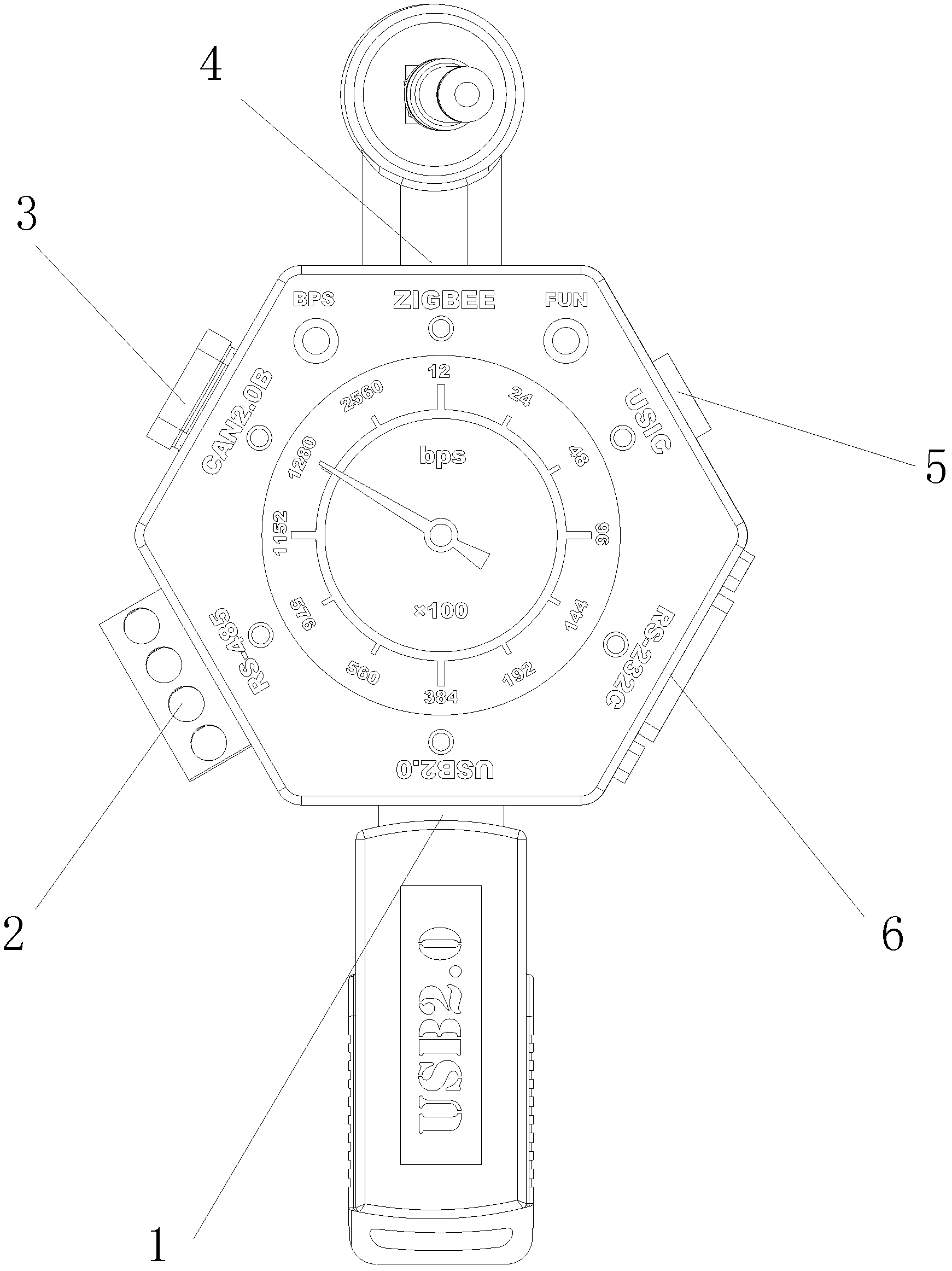
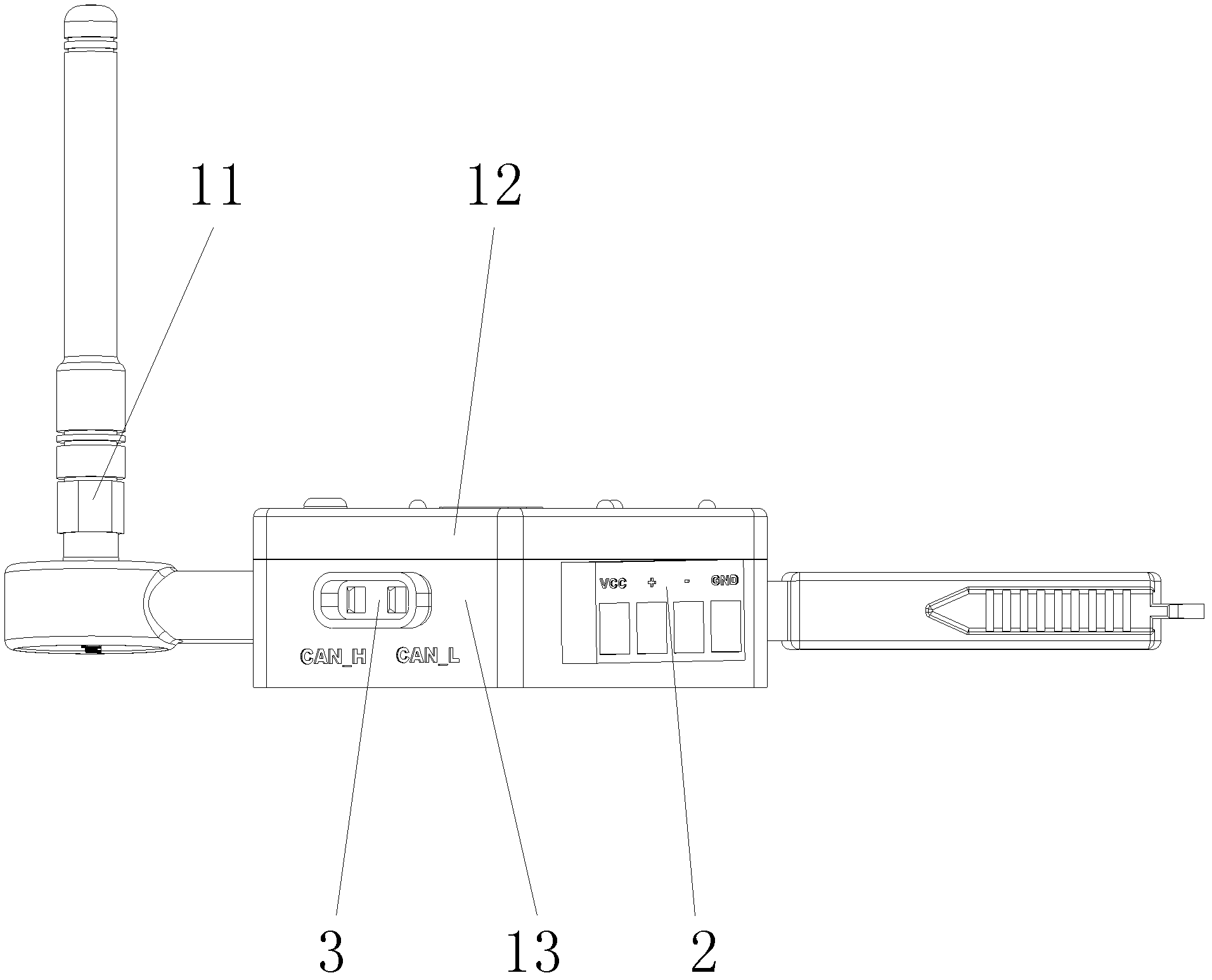
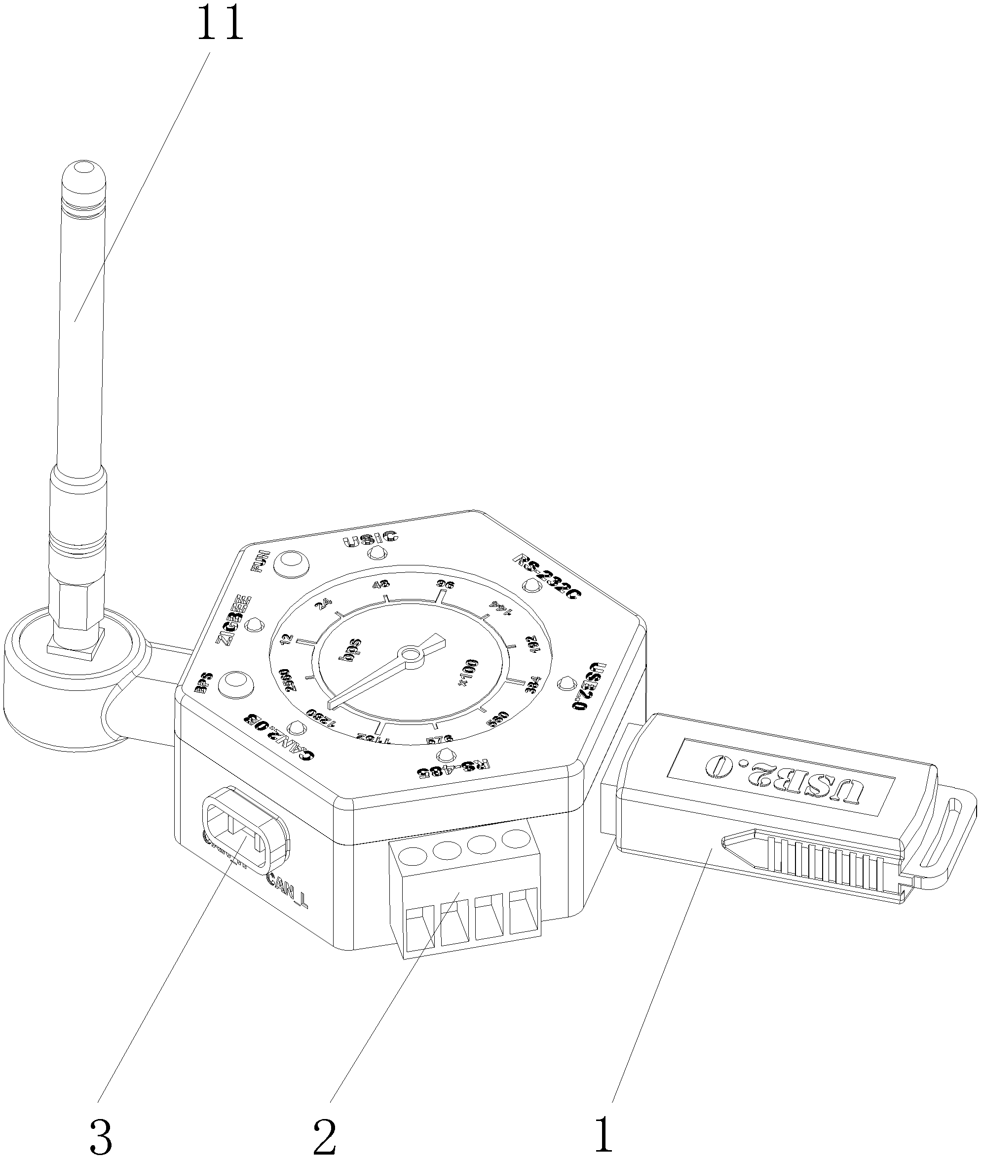
[0046] A multifunctional signal conversion network bridge, comprising a multifunctional signal conversion network bridge upper cover 12, a multifunctional signal conversion network bridge lower cover 13, a USB2.0 socket 1, an RS-485 socket 2, a CAN2.0B socket 3, and a ZIGBEE socket 4. USIC socket 5, RS-232C socket 6, baud rate BPS selection button 7, function FUN button 8, baud rate dial 9, baud rate scale pointer 10, ZIGBEE antenna 11 and built-in multi-function signal conversion Single-chip computer and micro stepping motor in the network bridge lower cover 13, its main points are: described multifunctional signal conversion network bridge is a hexahedral shape, respectively by a hexagonal multifunctional signal conversion network bridge loam cake 12 and A hexagonal multifunctional signal conversion bridge lower cover 13 is combined. Obv...


PUM


Abstract

A multifunctional signal transformation network bridge comprises a multifunctional signal transformation network bridge upper cover, a multifunctional signal transformation network bridge lower cover, a baud rate bit per second (BPS) selection button, a function (FUN) button, a baud rate dial gauge plate, a baud rate dial gauge indicator, a ZIGBEE antenna, a signal chip computer and a micro-step motor, wherein the signal chip microcomputer and the micro-step motor are arranged in the multifunctional signal transformation network bridge lower cover. The multifunctional signal transformation network bridge is characterized in that both the multifunctional signal transformation network bridge upper cover and the multifunctional signal transformation network bridge lower cover are in hexahedron structures, six side faces of the multifunctional signal transformation network bridge lower cover are respectively provided with a universal serial bus (USB) 2.0 socket, a radio station (RS)-485 socket, controller area network 2.0 B socket, a ZIGBEE socket, a united states information center (USIC) socket and a RS-232 C socket. A protocol signal can be transformed into a plurality of other protocol signals conveniently. The multifunctional signal transformation network bridge is mainly applicable to achievement of transformation interfaces and the like of various kinds of signals in electronic laboratories.

Description

technical field [0001] The invention relates to a multifunctional signal conversion network bridge, which is mainly used in electronic laboratories to realize conversion interfaces of various signals. Background technique [0002] With the rapid development of computer communication, industrial control and network technology, the field of information exchange and communication is rapidly covering all aspects of society. A variety of different communication interface protocol standards have emerged for different working environments. Among them, the most common ones are the serial physical interface standard RS-232C developed by the American Electronics Industry Association EIA, and the RS-485 standard used for industrial buses, following the "High-speed Control Local Area Network Digital Information Exchange Standard for Road Vehicles" formulated by the International Organization for Standardization The CAN2.0B protocol introduced, the ZIGBEE protocol for wireless LAN, and t...

Claims


Application Information

Patent Timeline
IPC IPC(8): H04L29/06
Inventor 不公告发明人
Owner SNTO TECH GRP
Why Eureka
Eureka Blog
Learn More