CAN-BUS integration control type electric control automobile chassis system

A CAN-BUS, integrated control technology, applied in the field of CAN-BUS integrated control electronically controlled automobile chassis system, can solve problems such as difficult to adapt to vehicle driving performance, inconvenient integrated control, scattered line connections, etc., and achieve easy real-time status monitoring and fault diagnosis, enhance work reliability, and realize the effect of integrated control

Inactive Publication Date: 2009-02-18
WANXIANG +1
View PDF0 Cites 3 Cited by
  • Summary
  • Abstract
  • Description
  • Claims
  • Application Information

AI Technical Summary

Problems solved by technology

[0003] The present invention mainly solves the technical problem that the chassis cannot be controlled as a control object in a whole sense due to the discrete control of each electronic control unit existing in the traditional automobile chassis electric control technology, which directly leads to vehicle ride comfort. , braking, handling stability, power and fuel economy cannot be effectively coordinated, and it is difficult to meet the requirements for further improvement of vehicle driving performance in all directions; instead, a CAN-BUS integrated control electronically controlled vehicle chassis system is provided, and relying on Based on the data transmission, sharing and integrated control of the chassis electronic control unit of the network, a CAN-BUS integrated control electronically controlled vehicle chassis system with less sensor redundancy, simplified electronic wiring harness layout, reduced weight and enhanced performance is formed.
[0004] The present invention also solves the technical problems existing in the prior art that some sensors of the chassis electric control device are repeatedly set, the line connections are scattered and complicated, it is not convenient for integrated control, and the reliability and fault diagnosis level of the control system are low.

Method used


Image

  • CAN-BUS integration control type electric control automobile chassis system
  • CAN-BUS integration control type electric control automobile chassis system

Examples


Embodiment Construction

[0017] The present invention will be further described below in conjunction with accompanying drawings and examples.

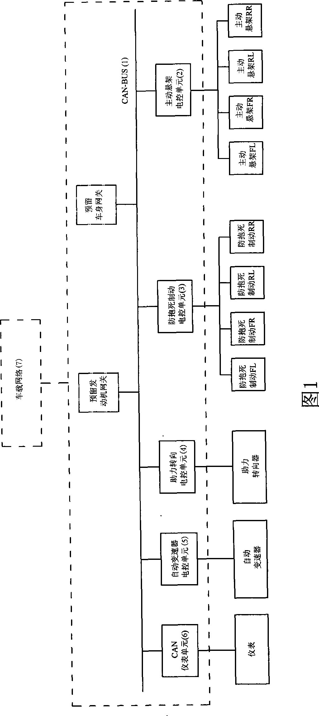
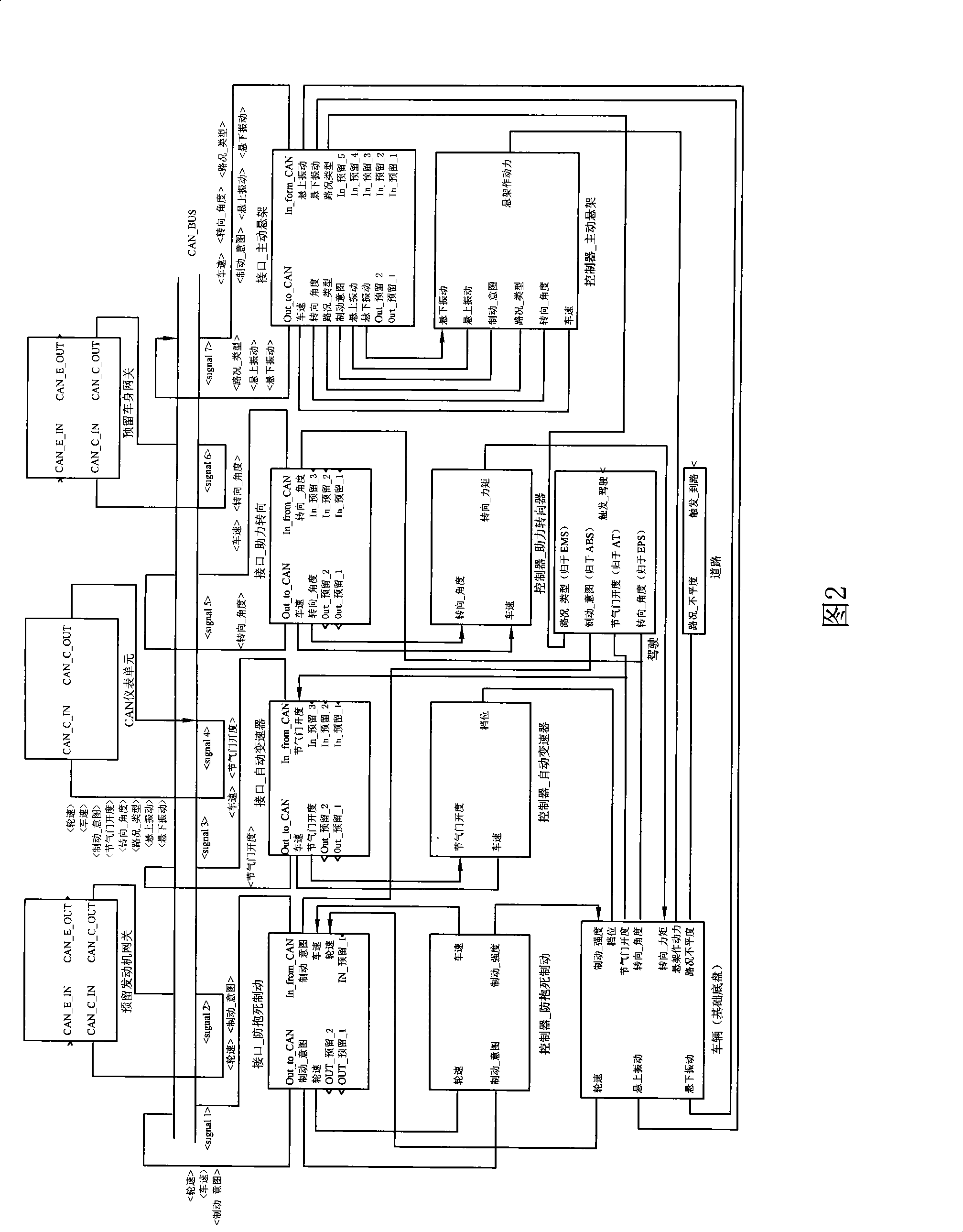
[0018] As shown in Figure 1, this CAN-BUS integrated control electronically controlled vehicle chassis system includes the suspension system, braking system, steering system, transmission system, instrument system, frame and auxiliary devices of the basic chassis. BUS1, and the active suspension electronic control unit 2 located in the suspension system, the anti-lock brake electronic control unit 3 located in the braking system, the power steering electronic control unit 4 located in the steering system, and the electronic control unit located in the transmission system The automatic transmission electronic control unit 5 and the CAN instrument unit 6 installed in the instrument system. And use CAN-BUS1 to interconnect active suspension electronic control unit 2, anti-lock braking electronic control unit 3, power steering electronic control unit 4, automatic ...


PUM


Abstract

The invention relates to an electric control automobile chassis, in particular to a CAN-BUS integrated control type electric control automobile chassis system, which comprises a suspension system, a brake system, a steering system, a transmission system, an instrument system, an automotive frame and an auxiliary device which are arranged on a basis chassis, and comprises an active suspension electric control unit arranged in the suspension system, an anti-blocking brake l electric control unit arranged in the brake system, an assistant steering electric control unit arranged in the steering system, an automatic transmission electric control unit arranged in the transmission system, and a CAN instrument unit arranged in the instrument system. The active suspension electric control unit, the anti-blocking brake electric control unit, the assistant steering electric control unit, the automatic transmission electric control unit and the CAN instrument unit are interconnected into an on-board network through the CAN-BUS. The electric control automobile chassis has the advantages of achieving the data transmission, data share and integration control to the automobile chassis electric control units, ensuring the tolerance of control system against failures, and the reliability of the entire automobile, carrying out real time status monitor and fault diagnosis easily and simple wire harness layout and reducing weight.

Description

Technical field [0001] The invention relates to the technical field of automobile chassis electric control, and mainly relates to a CAN-BUS integrated control type electric control automobile chassis system. Background technique [0002] At present, the electronic control technology of automobile chassis has been widely used. Chassis electronic control units such as electronically controlled active suspension systems, anti-lock braking systems, electronically controlled power steering systems, and automatic transmissions have increasingly become standing devices for high-end and mid-range models. , and the driving performance of the vehicle has been greatly improved. However, so far, even in some of the latest models, many of its chassis electronic control units still use the traditional mutual discrete control mode of work, which essentially separates the objective relationship between the relevant subsystems of the whole vehicle. The main problem brought about by the exis...

Claims


Application Information

Patent Timeline
Patent Type & Authority Applications(China)
IPC IPC(8): B60W10/00B60W10/18B60W10/20B60W10/22B60W10/10B60W30/02
Inventor 孙国辉资小林丁渭平黄建根
Owner WANXIANG
Why Eureka
Try Eureka