Electric heating glass kettle
A technology of electric heating glass and kettle, which is applied in the direction of ohmic resistance waterproof/airtight, ohmic resistance heating parts, water boiling utensils, etc. It can solve the problems of improving the production process of the pot body, damaging the glass body, glass burrs, etc. , to achieve the effect of reducing assembly process and tolerance requirements of accessories, improving assembly efficiency and reducing process requirements
- Summary
- Abstract
- Description
- Claims
- Application Information
AI Technical Summary
Problems solved by technology
Method used
Image
Examples
Embodiment 1
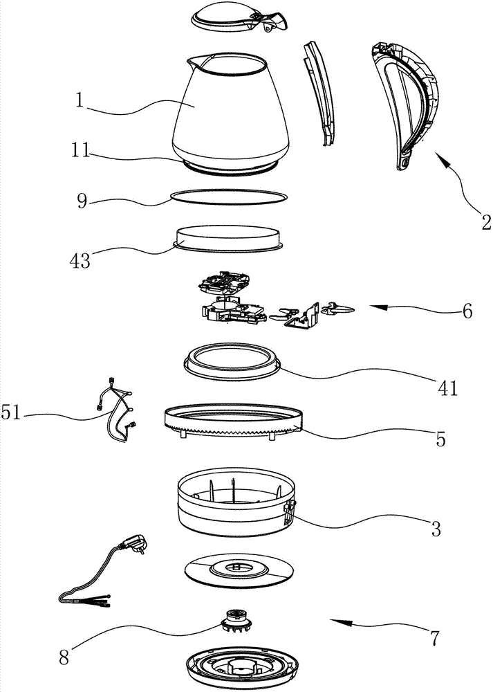
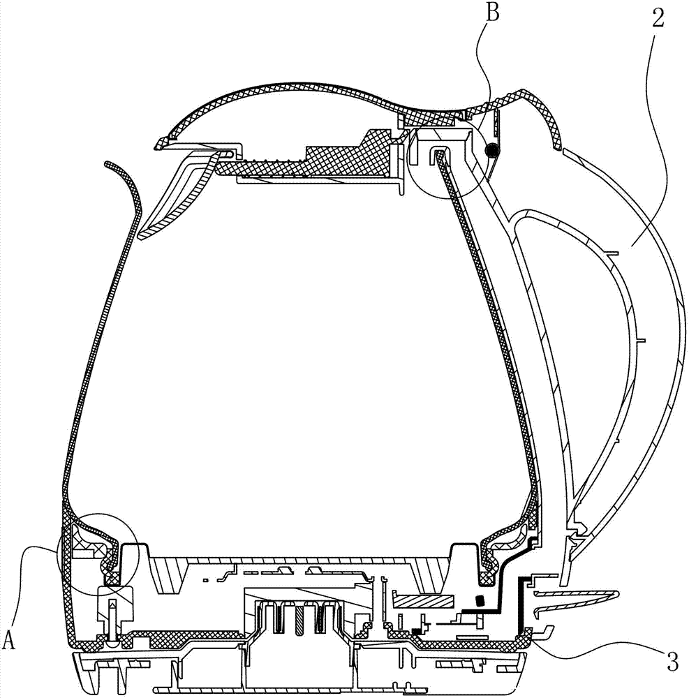
[0041] see Figure 1 to Figure 7According to the embodiment of the electric heating glass kettle provided by the present invention, it includes a glass cup body 1, a handle 2 and a bottom cover 3 arranged on the cup body 1, and a heating plate is installed at the bottom of the cup body 1, and the heating plate includes Body 41, heating element 42 and silicone ring 43 arranged on the body 41, a neck 11 is formed at the bottom of the cup body 1, and the silicone ring 43 is solidly connected to the body 41 and wraps the neck 11. The neck 11 is provided with a fastening ring 5, the bottom cover 3 is connected to the fastening ring 5, and the handle 2 is directly or indirectly connected to the fastening ring 5. The periphery of the body 41 is provided with an annular groove 411, and the silicone ring 43 is formed with an embedding portion 431 and an elastic wrapping portion 432, the embedding portion 431 is located in the annular groove 411, and above the embedding portion 431 An ...
Embodiment 2
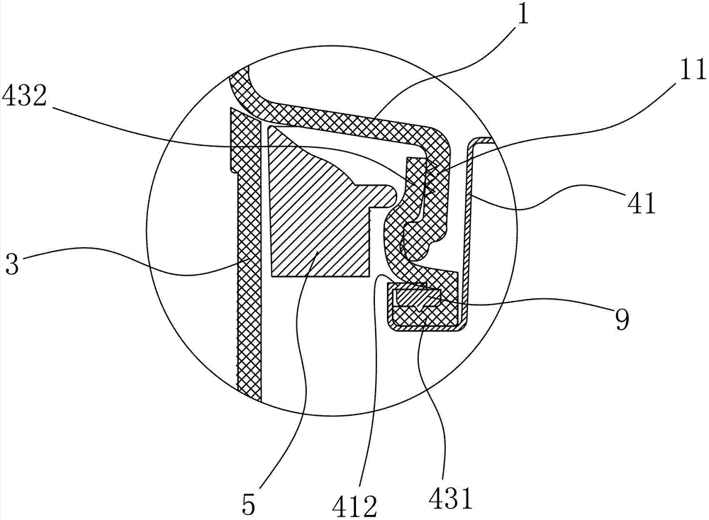
[0050] see Figure 8 , the structure of this embodiment is substantially the same as that of the first embodiment above, except that the solid-sealing connection structure between the silicone ring 43 and the body 41 is different. In this embodiment, the periphery of the body 41 is provided with an annular groove 411, and the silicone ring 43 An embedding portion 431 and an elastic wrapping portion 432 are formed on it, the embedding portion 431 is located in the annular groove 43, an annular pressure pad 9 is arranged in the embedding portion 431, and the outer end of the annular groove 411 faces toward The crimping portion 412 is formed by inward bending, the crimping portion 412 presses the embedding portion 431 , and the elastic wrapping portion 432 wraps the neck 11 . The bottom end of the annular pressure pad 9 is formed with ribs. The annular groove 411 of the main body 41 and the embedded part 431 of the silicone ring 43 are solidly sealed and connected by the above-m...
Embodiment 3
[0052] see Figure 9 , the structure of this embodiment is substantially the same as that of the first embodiment above, except that the solid-sealing connection structure between the silicone ring 43 and the body 41 is different. In this embodiment, the periphery of the body 41 is provided with an annular groove 411, and the silicone ring 43 An embedding portion 431 and an elastic wrapping portion 432 are formed on it, the embedding portion 431 is located in the annular groove 411, the outer end of the annular groove 411 is bent inward to form a crimping portion 412, the crimping The angle between the part 412 and the outer side of the annular groove 411 is less than 90 degrees, and the elastic wrapping part 432 wraps the neck 11 . The annular groove 411 of the main body 41 and the embedded part 431 of the silicone ring 43 are sealed and connected by the above structure, the processing technology is simple, and the sealing effect is good. The angle is preferably set at 60 de...
PUM
 Abstract
Description
Claims
Application Information
 - R&D
- Intellectual Property
- Life Sciences
- Materials
- Tech Scout
- Unparalleled Data Quality
- Higher Quality Content
- 60% Fewer Hallucinations
Browse by: Latest US Patents, China's latest patents, Technical Efficacy Thesaurus, Application Domain, Technology Topic, Popular Technical Reports.
© 2025 PatSnap. All rights reserved.Legal|Privacy policy|Modern Slavery Act Transparency Statement|Sitemap|About US| Contact US: help@patsnap.com


