Crystal blank automatic polishing system and docking mechanism thereof

A docking mechanism and docking machine technology, applied in grinding/polishing equipment, grinding machines, spherical grinders, etc., can solve problems such as low processing efficiency, difficulty in removing fixtures, and long waiting time, so as to improve processing efficiency and ensure bonding Firmness and the effect of shortening the occupation time

Active Publication Date: 2013-05-22
虞雅仙
View PDF16 Cites 5 Cited by
  • Summary
  • Abstract
  • Description
  • Claims
  • Application Information

AI Technical Summary

Problems solved by technology

The two fixture holders that are docked in this way slide along the same guide rail, which can ensure higher docking accuracy, but because it is difficult for the manipulators of each station transfer mechanism to remove the clamps on the lower fixture holders, and in order to realize each The overall cycle between the processing stations, so the docking mechanism is generally set to a structure in which the upper and lower fixture fixing seats can be reversed up and down (that is, the mounting plate is set to be able to turn up and down), so that only one manipulator of each station transfer mechanism is needed. Moreover, only one fixture is picked up at a time on the docking station (that is, single fixture circulation), and an empty fixture will always be reserved on the docking mechanism (that is, the fixture with the crystal blank becomes an empty fixture after docking), and the empty fixture must be The crystal blank can only be bonded after being powdered (that is, it is docked with another fixture with the crystal blank fixed on it). Therefore, this form of docking process must include the clamp needle preheating of the fixture, the powder feeding of the powder plate and the fixture of the fixture. There are three actions of needle powder dipping (that is, the docking mechanism must include a powder feeding device), which leads to a much longer time for docking at the docking station than for grinding, polishing, loading or unloading at other stations. The waiting time of the station is long, and the overall processing efficiency is low

Method used


Image

  • Crystal blank automatic polishing system and docking mechanism thereof
  • Crystal blank automatic polishing system and docking mechanism thereof
  • Crystal blank automatic polishing system and docking mechanism thereof

Examples


Embodiment 1

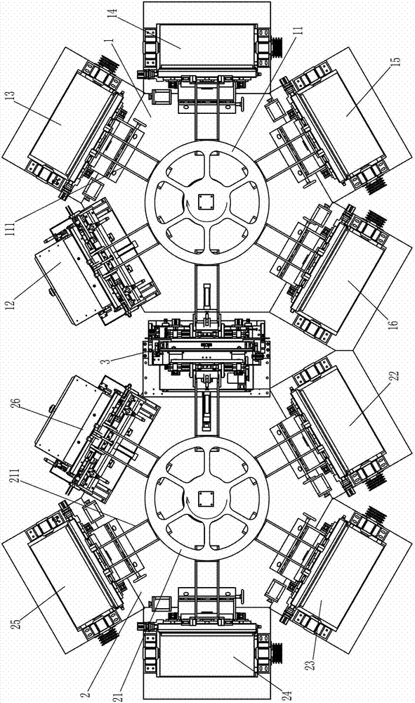
[0032] Such as figure 1 A kind of crystal blank automatic grinding and polishing system shown, comprises: the first rotating frame 11 that is installed on the first frame 1, is provided with feeding station 12, two pairs of crystal blanks around the first rotating frame 11 The upper hemisphere grinding station 13,14 for grinding the upper hemisphere of the upper hemisphere of the crystal blank, the upper hemisphere polishing station 15,16 and the docking station 3 for polishing the upper hemisphere of the crystal blank, the first rotating frame 11 It can be rotated and positioned and is provided with six manipulators 111 capable of picking up and putting down fixtures; the second rotating frame 21 installed on the second frame 2 is provided with the docking station 3, two Lower hemisphere grinding stations 22, 23 for grinding the lower hemisphere of the crystal blank, two lower hemisphere polishing stations 24, 25 and blanking station 26 for polishing the lower hemisphere of t...

Embodiment 2

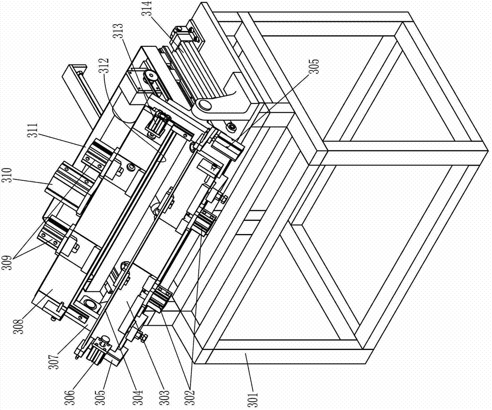
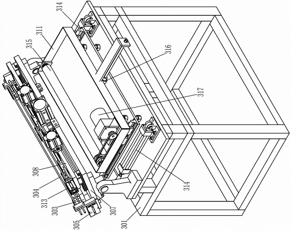
[0037] An automatic grinding and polishing system and docking mechanism for crystal blanks, the only difference from Embodiment 1 is that the mounting plate 307 has two rotation stop positions: when the mounting plate 307 rotates to the first rotation stop position, the mounting plate 307 is In the vertical state, the second clamp seat 308 is located above the first clamp seat 303; as Figure 7 As shown, when the mounting plate 307 rotates to the second rotation stop position, the mounting plate 307 is in a horizontal state, and the first clamp seat 303 and the second clamp seat 308 are both on the mounting plate 307 .

Embodiment 3

[0039] An automatic grinding and polishing system for crystal blanks, comprising: a first rotating frame, at least one upper hemisphere grinding station for grinding the upper hemisphere of the crystal blank and at least one pair of crystal blanks are arranged around the first rotating frame The upper hemisphere polishing station for polishing the upper hemisphere of the workpiece, the first rotating frame can be rotated and positioned and is provided with at least two machine heads capable of installing fixtures; the second rotating frame is provided with at least one pair of The lower hemisphere grinding station for grinding the lower hemisphere of the crystal blank and at least one lower hemisphere polishing station for polishing the lower hemisphere of the crystal blank, the second rotating frame can be rotated and positioned and is provided with at least two A machine head capable of installing fixtures; feeding station is provided with a feeding mechanism that can fix the...


PUM


Abstract

The invention discloses a docking mechanism. The docking mechanism comprises a docking rack and an installing plate, wherein the installing plate is provided with a first clamp seat and a second clamp seat. The first clamp seat is fixedly connected with the installing plate, the second clamp seat is connected with the installing plate in a sliding mode and is driven through a sliding driving device, the first clamp seat and the second clamp seat are both provided with a clamp positioning device and a clamp locking device, and a rotary shaft of the installing plate is horizontally arranged and located between the first clamp seat and the second clamp seat. The installing plate is driven to rotate by a rotating driving device which is installed on the docking rack. The installing plate has two rotating stop positions: a vertical state that the second clamp seat is located above the first clamp seat, and a heeling or horizontal state that the first clamp seat and the second clamp seat are both arranged on the installing plate. The invention further discloses a crystal blank automatic polishing system adopting the docking mechanism. By the technical scheme, the docking precision is high, bonding is firm, a mechanical arm structure action is convenient to design, and the docking efficiency and the processing efficiency of the whole automatic polishing system are improved.

Description

technical field [0001] The invention belongs to the field of grinding and polishing of crystal products, and relates to an automatic grinding and polishing system for crystal blanks for automatic grinding and polishing of crystal blanks, in particular to a docking mechanism for the automatic grinding and polishing system for crystal blanks. Background technique [0002] In the prior art, the automatic grinding and polishing system (grinding and polishing machine) of crystal blanks includes: a feeding station, which is provided with a feeding mechanism capable of fixing the crystal blanks on the fixture; The upper hemisphere grinding station for grinding the hemisphere and at least one upper hemisphere polishing station for polishing the upper hemisphere of the crystal blank; the docking station is provided with the ability to transfer and fix the crystal blank from a fixture to On the other fixture, a docking mechanism capable of exchanging the positions of the two fixtures;...

Claims


Application Information

Patent Timeline
Patent Type & Authority Applications(China)
IPC IPC(8): B24B11/00B24B41/06
Inventor 虞卫东
Owner 虞雅仙
Why Eureka
Try Eureka