
Screen printing plate conveying mechanical hand device of printing production line
A production line and manipulator technology, applied in the direction of manipulators, program-controlled manipulators, chucks, etc., can solve problems such as insufficient efficiency, high labor intensity, poor working environment, etc., and achieve the effect of fast action, reduced collision force, and simple operation
Patent Information
- Authority / Receiving Office
- CN · China
- Patent Type
- Applications(China)
- Current Assignee / Owner
- Publication Date
- 2013-05-22
Smart Images
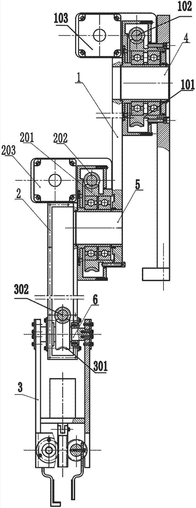
Figure 1 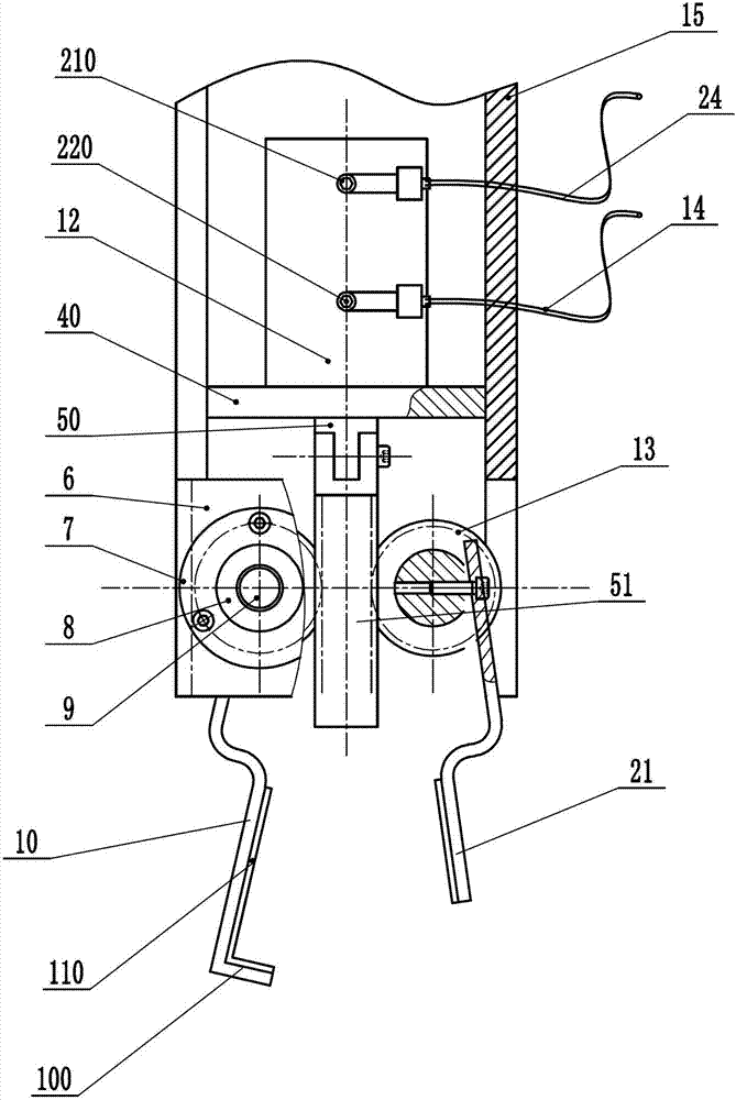
Figure 2 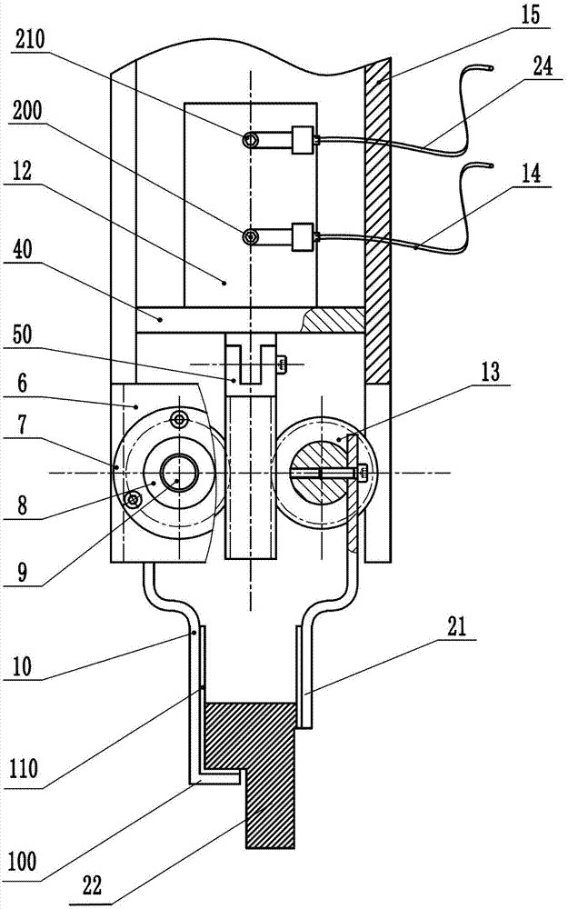
Figure 3
Abstract
Description
technical field
[0001] The invention relates to a screen transfer device for a printing production line, in particular to a screen transfer device with a manipulator. Background technique
[0002] The textile printing and dyeing industry is one of the important industries of my country's national economy. There are many types of dyeing and finishing equipment. Among them, the flat screen printing machine is widely used in the printing field of our country because of its large pattern and high precision, and it has greatly improved the printing and dyeing industry. The level of automation is still high, but there are still many stages in the front and rear processes of printing that are completed by manpower. At the production site, the printing screens are taken and placed very frequently, and some printing screens with large flowers need two or more people to pick and place. This manual handling method is not only labor-intensive, but also has a poor working environment and ...
Examples
Embodiment Construction
[0027] specific implementation plan
[0028] The present invention will be described in detail below in conjunction with the accompanying drawings and specific embodiments.
[0029] The present invention comprises a pneumatic manipulator mechanism, a base 11, a three-joint manipulator slidably connected to one end of the base 11, and a base stop cylinder 70 connected to the other end of the base 11, and the base is fixed on the base stop cylinder 70 for the action stroke. On the guide rail slide block 91 of the linear guide rail 90 on the extension line, thereby can control the back and forth motion of base on the linear guide rail by controlling the action of stopper cylinder. Such as image 3 As shown, when the left end of the base stop cylinder 70 intake air, the cylinder rod 8 pushes the base 11 to translate a stroke of the base stop cylinder 70 to the right on the linear guide rail 90, and completes the extending action of the manipulator mechanism; After the action is ...