Pile position deviation real time detecting device

A real-time detection and deviation technology, which is applied in the test of infrastructure, construction, infrastructure engineering, etc., can solve the problems of difficult to find deviation value, high detection cost, and difficult to obtain deviation direction, so as to facilitate the inspection personnel and the inspection. The effect of wide range and low detection cost

Active Publication Date: 2013-05-22
黄吉永
View PDF6 Cites 4 Cited by
  • Summary
  • Abstract
  • Description
  • Claims
  • Application Information

AI Technical Summary

Problems solved by technology

[0003] 1. It is cumbersome to set up theodolites in the direction of the two axes perpendicular to the pile position. It is expensive to configure two theodolites and at least two surveyors at the same time.
[0004] 2. If the deviation of the pile driving process occurs on one of the two orthogonal axes, one of the surveyors will observe the pile deviation information, but another person needs to cooperate with the pile root to measure the deviation value with a ruler. This is both inconvenient and human error, and the probability of deviation in only one axis direction is not high
[0005] 3. When the pile sinking process generates deviation values ​​on two orthogonal axes at the same time, it is necessary to measure the deviation values ​​in two directions. The possibility of deviation measurement error is greater, and the deviation direction of the pile is not easy to obtain.
[0006] 4. If the circular cross-section pile is deviated, the accuracy of the deviation value of the measuring ruler is even more difficult to guarantee
[0007] 5. The possibility of errors caused by manual field measurement of deviation values ​​is high, and small deviation values ​​are not easy to find, nor can they continuously reflect deviation values, which affects the timely correction of pile position deviations in the pile sinking process

Method used


Image

  • Pile position deviation real time detecting device
  • Pile position deviation real time detecting device
  • Pile position deviation real time detecting device

Examples


Embodiment Construction

[0023] The present invention will be further described in detail below with reference to the embodiments of the accompanying drawings.

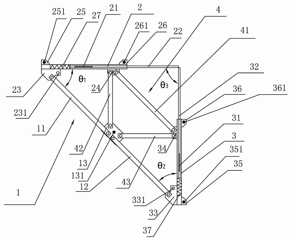
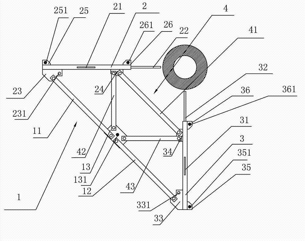
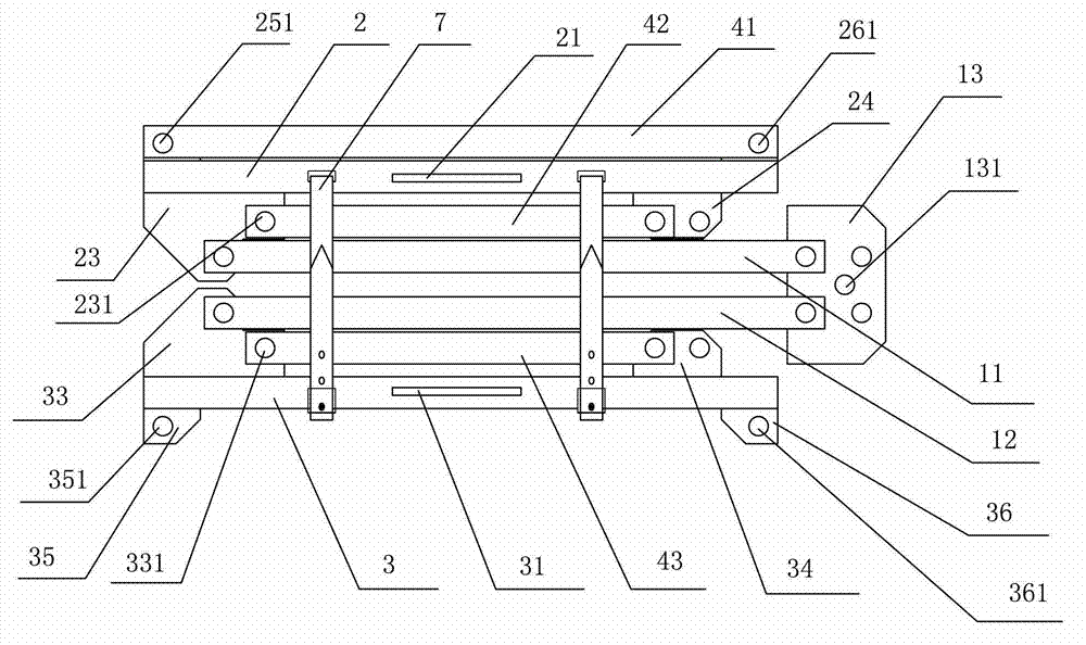
[0024] As shown in the figure, a real-time detection device for pile position deviation includes a main support rod 1, a first detection rod 2 and a second detection rod 3, the first detection rod 2 and the second detection rod 3 have the same length, and the first detection rod 2 is made of a metal square tube, the first detection rod 2 is provided with a first level tube 21 and a first sliding scale 22 that can be extended and retracted along the axial direction of the first detection rod 2, and the first sliding scale 22 is installed on the metal square tube. In the tube core, a first spring 27 is arranged between the first detection rod 2 and the first sliding scale 22, the second detection rod 3 is made of a metal square tube, and a second level tube 31 is arranged on the second detection rod 3 and a second sliding scale 32 that can be e...


PUM


Abstract

The invention discloses a pile position deviation real time detecting device. The pile position deviation real time detecting device is characterized by comprising a main supporting rod, a first detecting rod and a second detecting rod. The length of the first detecting rod is the same with the length of the second detecting rod. A first sliding calibrated scale capable of stretching along the first detecting rod in the axial direction is arranged on the first detecting rod. A second sliding calibrated scale capable of stretching along the second detecting rod in the axial direction is arranged on the second detecting rod. A first elastic restoring mechanism is arranged between the first detecting rod and the first sliding calibrated scale. A second elastic restoring mechanism is arranged between the second detecting rod and the second sliding calibrated scale. An inclined angle with 45 degrees is formed between the first detecting rod and the main supporting rod. An inclined angle with 45 degrees is formed between the second detecting rod and the main supporting rod. An inclined angle with 90 degrees is formed between an extending line of the first detecting rod and an extending line of the second detecting rod. A relative location fixing mechanism is arranged among the main supporting rod, the first detecting rod and the second detecting rod. The pile position deviation real time detecting device has the advantages of being simple in structure, convenient to use and capable of observing the deviation value in real time. Staff are little. Detecting cost is low.

Description

technical field [0001] The invention relates to a building construction detection device, in particular to a real-time detection device for pile position deviation. Background technique [0002] It is one of the basic rules of building structure design that the geometric centroid of the pile level plane in the pile cap coincides with the centroid of the horizontal section of the vertical force-transmitting member of the structure above it. The geometric centroid does not coincide with the centroid of the horizontal section of the vertical force-transmitting member, resulting in the fact that the load ratio actually distributed to each pile in the cap is inconsistent with the design condition, and the cap structure generates additional internal forces such as bending moment and torque. If the deviation value of the position exceeds the specified value of the construction quality acceptance specification, it must be compensated by measures such as capping reinforcement and pil...

Claims


Application Information

Patent Timeline
Patent Type & Authority Applications(China)
IPC IPC(8): E02D33/00
Inventor 黄吉永郑荣跃黄楠
Owner 黄吉永
Why Eureka
Try Eureka