Mass flow piezoelectric straight moving hydraulic reliever

A technology of decompression device and high flow rate, applied in transmission control, components with teeth, belts/chains/gears, etc., it can solve the problem of affecting decompression accuracy, output flow and high-speed response, which cannot satisfy the shifting control hydraulic system. , structural limitations and other issues, to achieve the effect of improving the decompression speed and voltage stabilization accuracy, ingenious design, and reducing vibration

Inactive Publication Date: 2013-05-22
CHINA NORTH VEHICLE RES INST
View PDF6 Cites 4 Cited by
  • Summary
  • Abstract
  • Description
  • Claims
  • Application Information

AI Technical Summary

Problems solved by technology

At the same time, due to structural limitations, pilot control is generally used in the design of large-flow decompression devices in China, which will inevitably affect the decompression accuracy to a certain extent; while the existing advanced electro-hydraulic proportional decompression control valves are limited in output flow and high-speed response. Unable to meet the requirements of the shift control hydraulic system

Method used


Image

  • Mass flow piezoelectric straight moving hydraulic reliever
  • Mass flow piezoelectric straight moving hydraulic reliever
  • Mass flow piezoelectric straight moving hydraulic reliever

Examples


Embodiment Construction

[0016] The present invention will be described in more detail below in conjunction with the accompanying drawings and specific embodiments.

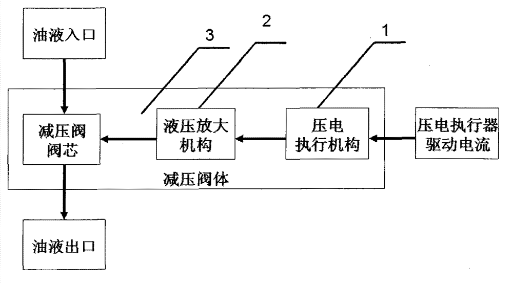
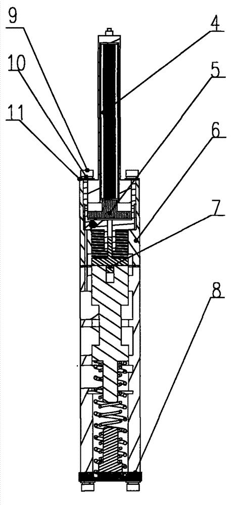
[0017] Such as figure 2 As shown, the large-flow piezoelectric direct-acting hydraulic decompression device of the present invention includes a piezoelectric actuator 4, a hydraulic amplifying mechanism 5 and a decompression valve body. The pressure reducing valve body includes an upper pressure reducing valve body 6 and a lower pressure reducing valve body 8. The upper pressure reducing valve body 6 is equipped with a piezoelectric actuator 4 and a hydraulic amplifying mechanism 5 sequentially from top to bottom. The upper pressure reducing valve body 6 It is fixedly connected with the lower pressure reducing valve body 8 through the connecting bolt 9, and a spring washer 10 and a flat pad 11 are installed at the joint of the connecting bolt 9, and paper is used between the joint surface of the upper pressure reducing valve body 6 and ...


PUM


Abstract

The invention relates to a mass flow piezoelectric straight moving hydraulic reliever. Voltage reduction and voltage stabilizing functions can be simultaneously achieved. Shift control accuracy and improvement of buffer precision are effectively guaranteed. The hydraulic reliever comprises a piezoelectric actuating mechanism (4), a hydraulic amplification mechanism (5) and a voltage reducing valve. The voltage reducing valve comprises an upper voltage reducing valve (6) and a lower voltage reducing valve (8). The piezoelectric actuating mechanism comprises a piezoelectric actuator (14), a terminal nut (13) and a piezoelectric actuator outer cover (12). The hydraulic amplification mechanism comprises a piston rod (15), a big piston (16), a small piston (20), and a small piston spring (21). The piezoelectric actuating mechanism (4) and the hydraulic amplification mechanism (5) are arranged inside the upper voltage reducing valve (6) in sequence from top to bottom. The upper voltage reducing valve (6) and the lower voltage reducing valve (8) are fixedly connected through a connecting bolt (9).

Description

technical field [0001] The invention relates to the field of an oil pressure decompression device for comprehensive transmission shift control, in particular to a large-flow piezoelectric direct-acting hydraulic pressure decompression device. The decompression device can realize the decompression and pressure stabilization functions of a hydraulic system at the same time. Background technique [0002] Whether the outlet pressure of the decompression device is stable or not and whether the decompression speed is fast or not in the integrated transmission shifting control hydraulic system have a major impact on the shifting operation accuracy and buffering accuracy. The decompression device currently used is the traditional hydraulic control decompression device. , the control is difficult, the response is slow, and it is easy to wear and get stuck, and it is not easy to correct, which can easily lead to system failure. The piezoelectric drive mechanism can achieve high-respon...

Claims


Application Information

Patent Timeline
Patent Type & Authority Applications(China)
IPC IPC(8): F16H61/4008
Inventor 熊庆辉顾宏弢罗小梅李娟王敏韩颜莹潘嘉明
Owner CHINA NORTH VEHICLE RES INST
Why Eureka
Try Eureka