
Distributed direct current independent power supply system

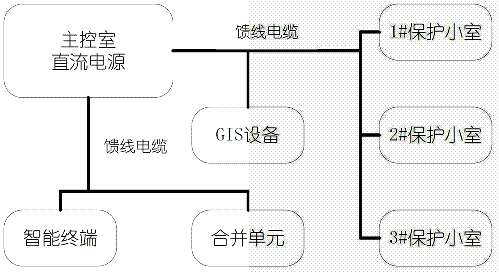
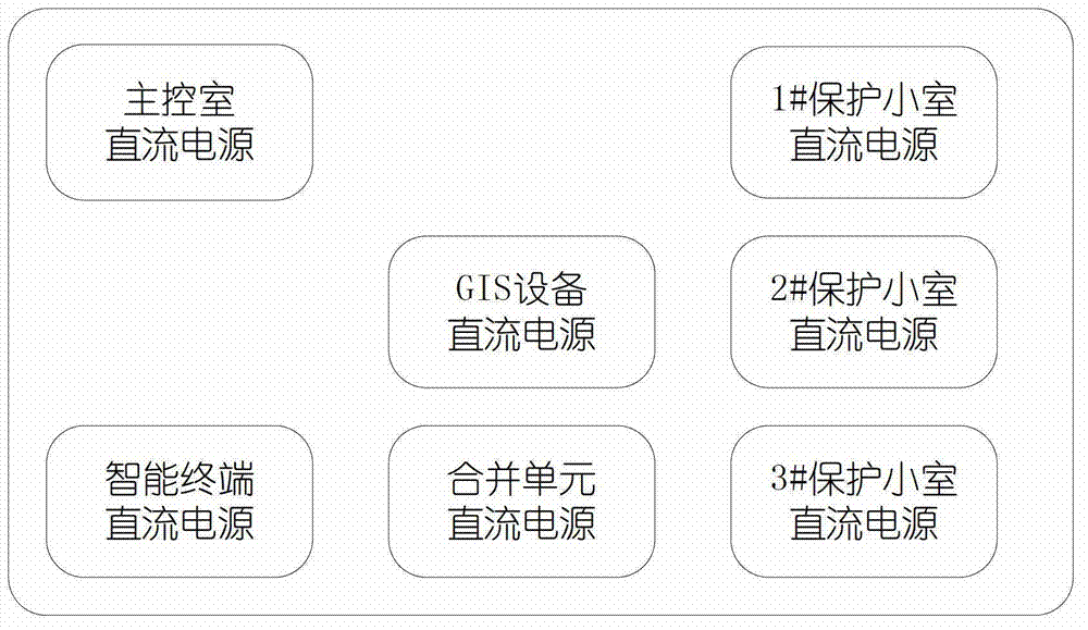
A power supply system and distributed technology, applied in the direction of current collectors, electric vehicles, electrical components, etc., can solve the problems of cumbersome information processing, troublesome battery replacement and maintenance, and many fault points, etc. Clarity, gradation and simple effects

Active Publication Date: 2013-05-22
SHANDONG LUNENG SOFTWARE TECH
View PDF7 Cites 9 Cited by
  • Summary
  • Abstract
  • Description
  • Claims
  • Application Information

AI Technical Summary

Problems solved by technology

Distributed capacitance makes the line capacitive when the line is unloaded. If it is too large, it will affect the accuracy of branch circuit insulation detection, cause false alarms for branch circuit grounding, and increase the voltage at the end, causing damage to the insulation of power equipment and affecting the anti-electromagnetic interference of the equipment. ability
More importantly, when the capacitive current generated by the distributed capacitance is too large, when a point is grounded in the secondary circuit, it may also cause the protection equipment to malfunction.
[0007] 2) The selective coordination of the upper and lower protection devices cannot be realized between the systems (gradual coordination)
[0008] The DC power supply system has a lot of power supply equipment, and the feeder branches are widely distributed. There are many branches in the system that need to be protected by circuit breakers or fuses. This distributed DC uninterruptible power supply system connects the subsystems together through the DC bus. Realize the reasonable cooperation between choosing the correct protection scheme and protecting the upper and lower levels
Leading to leapfrog tripping and magnifying the power accident
[0009] 3) The operating condition of the system battery is unclear
[0010] Whether it is a centralized DC power supply system or a distributed DC uninterruptible power supply system, the battery packs are always in a floating charge standby state. It is detected by resistance patrol inspection and checking charge and discharge. This detection method has poor real-time performance and cannot make judgments on the working condition of the battery in the first place. In addition, it is more troublesome to replace and maintain the faulty battery online, and there are certain potential safety hazards.
[0011] 4) The system design is complex and there are many failure points
[0012] The design of this distributed DC uninterruptible power supply system is relatively complicated; the DC bus is divided into multiple sections, and multiple switches need to be switched on and off when maintaining the bus or charging and discharging the battery pack, which increases the failure points of the system, and the networked DC bus power supply is easy. Causes the mutual movement between the various sections of the DC bus. Once these problems appear, not only will it cause serious damage to the electrical equipment, but it will be difficult for the operating personnel to conduct timely investigations, let alone online maintenance.
[0013] 5) Lack of an effective monitoring system
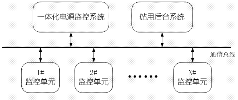
[0014] Chinese patent application 201110130055.0 is that the communication unit in the subsystem communicates with the host computer in the station through RS485 or CAN bus or Ethernet port. The information processing is cumbersome and lacks overall information processing and monitoring.

Method used


Image

  • Distributed direct current independent power supply system
  • Distributed direct current independent power supply system
  • Distributed direct current independent power supply system

Examples


Embodiment 1

[0079] Such as Figure 4 The shown DC subsystem includes a section of DC bus, which is connected to the feeder terminal unit. The DC bus is configured with: 1# battery pack and 2# battery pack connected in parallel, a charging unit and a monitoring unit.

[0080] When the 1# battery pack supplies power and the 2# battery pack is charging, the switch K1 and switch K4 are turned off, and the switch K2 and switch K3 are closed; when the 2# battery pack is fully charged, the switch K3 is turned off, and the 2# battery pack is in the standby state. When the power of the 1# battery pack is insufficient, the system will automatically switch to the 1# battery pack powered by the 2# battery pack for charging. At this time, the switch K1 and switch K4 are closed, and then the switch K2 is turned off, and the charging unit charges the 1# battery pack. After charging, the switch K1 is turned off, and the 1# battery pack is in hot standby state.

[0081] If the charging unit is abnormal, ...

Embodiment 2

[0088] Such as Figure 5 The only difference between the shown DC subsystem and Embodiment 1 is that each set of storage batteries is connected to the busbar through two sets of thyristor switching devices, which serve as backups for each other and increase the reliability of the busbar.

Embodiment 3

[0090] Such as Figure 6The only difference between the shown DC subsystem and Embodiment 1 is that the system adds two sets of accumulators, 3# battery pack and 4# battery pack, and the two sets of accumulators are connected to the bus for power supply at the same time during normal operation. The method of ×2 is alternately input, and the charging unit charges the two separated batteries in sequence to increase the reliability of the battery pack.


PUM


Abstract

The invention discloses a distributed direct current independent power supply system which breaks up a whole direct current power supply system into parts, reasonably divides the direct current power supply system into a plurality of independent operating direct current power supply subsystems, and is arranged to be nearby electricity utilization equipment. The distributed direct current independent power supply system comprises a communication bus, a master control system, a plurality of independent direct current power supply subsystems, a plurality of box-type packaged parallel-connection battery packs, at least one charging unit and at least one monitoring unit, wherein the master control system and the plurality of independent direct current power supply subsystems are respectively connected with the communication bus. Each direct current power supply subsystem comprises a plurality of sections of direct current buses connected with a feeder line terminal unit, and every two sections of adjacent direct current buses are connected through a switch and are allocated. The output ends of the battery packs are respectively connected to the direct current buses through the switches. The at least one charging unit is used for charging all the battery packs and supplies electricity to the direct current buses in hot spare mode. The at least one monitoring unit is connected onto the communication bus, measures and upwards transmits signals of the direct current power supply subsystems to the master control system and receives power grid electricity utilization information of the master control system.

Description

technical field [0001] The invention relates to a distributed direct current independent power supply system. Background technique [0002] At present, the DC power supply system generally adopts the design mode of three chargers and two batteries, 220V DC bus segment and contact switch. The DC power supply subsystem on the bus supplies power to the electrical equipment, which is a traditional centralized DC power supply system. As a centralized DC power supply system, it is more likely to cause insulation degradation or large-area multiple branch circuits to be grounded at the same time. What is more critical is that when multiple points are grounded in the secondary circuit of the same electrical connection, different points will appear before Potential difference, when there is a short-circuit fault, it may cause the differential protection to malfunction or the protection will refuse to operate. [0003] Chinese patent application 201110130055.0 discloses a distributed...

Claims


Application Information

Patent Timeline
IPC IPC(8): H02J11/00H02J7/34H02J3/28
Inventor 姜志鹏刘宁刘耀辉孟祥军梁鹏
Owner SHANDONG LUNENG SOFTWARE TECH
Learn More