Control apparatus for a first tool and a second tool

A technology for working tools and control devices, which is applied to fluid pressure actuating devices, servo motors, servo meter circuits, etc., to achieve the effects of simplified structure, simple cost, and reduced structural expenses

Active Publication Date: 2013-05-22
LUKAS HYDRAULIK
View PDF8 Cites 6 Cited by
  • Summary
  • Abstract
  • Description
  • Claims
  • Application Information

AI Technical Summary

Problems solved by technology

In practice, this results in the operator having to move the operating levers of the two control valves in the required manner

Method used


Image

  • Control apparatus for a first tool and a second tool
  • Control apparatus for a first tool and a second tool
  • Control apparatus for a first tool and a second tool

Examples


Embodiment Construction

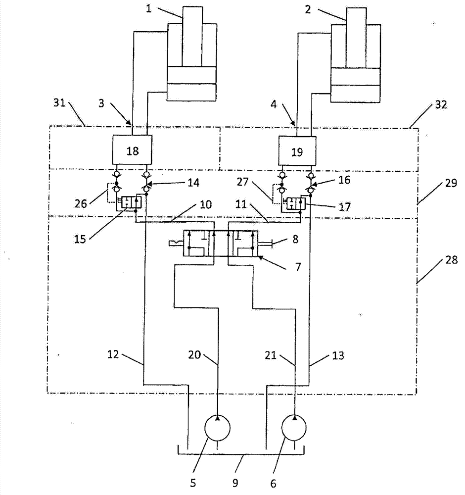
[0032] figure 1 The reference numerals 1 and 2 in the figure designate a first or a second power tool, in particular a rescue shear and a rescue separator. The first power tool 1 is supplied with pressure medium, in particular hydraulic oil, via the first supply circuit 3 , and the second power tool 2 is supplied with pressure medium, in particular hydraulic oil, via the second supply circuit 4 . To actuate the two power tools 1 , 2 , the first actuating valve 18 or the second actuating valve 19 is connected to the respective power tool 1 , 2 via a pressure line or a pressure relief line. The control valves 18 , 19 are used to interrupt the pressure supply to the power tools 1 , 2 or to reverse the direction of the pressure supply if necessary.

[0033] If necessary, the actuating valves 18, 19 can be expediently arranged in the associated valve block 31 or 32, e.g. figure 1 shown in .

[0034] The pressure generation takes place via a first pressure generating device 5 and...


PUM


Abstract

The invention relates to a control apparatus for a first and a second tool (1, 2) operated by means of a pressure medium, in particular hydraulic oil, comprising a first supply circuit (3) for the first tool (1) and a second supply circuit (4) for the second tool (2). The control apparatus is or at least can be connected to a first pressure line (20) and to a second pressure line (21) of a control device to be operated in particular manually, by means of which control device the flow rate at the first tool (1) and at the second tool (2) can be changed.; In order to improve the usability and to simplify the design, a novel control device is proposed, which is characterized in that a control valve (7) is provided jointly for the first and second supply circuits (3, 4) as the control device, the control valve (7) has three switching positions, namely: (a) the flow rate from the first pressure line (20) is available only to the first tool (1) and the flow rate from the second pressure line (21) is available only to the second tool (2), (b) the flow rate from the first and second pressure lines (20, 21) is available preferably to the first tool (1), (c) the flow rate from the first and second pressure lines (20, 21) is available preferably to the second tool (2).

Description

technical field [0001] The invention relates to a control or regulating device according to the preamble of claim 1 . Background technique [0002] Such a control device is used, for example, to drive a plurality of power tools in parallel, such as life shears and life separators. In this case, the operator operates the control device in accordance with the requirements of other operators who operate the respective power tool connected to the control device. Thus, for example, in a car accident, one member of the rescue team operates the control device, while another member of the rescue team cuts, for example, the roof suspension of the accident vehicle directly on the accident vehicle by means of life-saving shears and another member of the rescue team With the aid of rescue separators, personnel attempt to provide more space in the interior of the accident vehicle in order to rescue, for example, trapped passengers. For this application, the good operability of the cont...

Claims


Application Information

Patent Timeline
Patent Type & Authority Applications(China)
IPC IPC(8): F15B11/17
CPCF15B2211/7053F15B2211/781F15B2211/2654F15B11/17
Inventor W·贝特莱夫C·绍尔比尔
Owner LUKAS HYDRAULIK
Why Eureka
Try Eureka