Reduction device

A technology of reduction gear and eccentric circle, which is applied in the direction of transmission, gear transmission, shaft installation, etc., can solve the problem of longer axial length of the reduction gear, and achieve the effect of reducing resistance and cost

Active Publication Date: 2013-05-22
NTN CORP
View PDF7 Cites 6 Cited by
  • Summary
  • Abstract
  • Description
  • Claims
  • Application Information

AI Technical Summary

Problems solved by technology

Therefore, the axial length of the reduction gear becomes longer and larger, leaving room for improvement in miniaturization of the axial length.

Method used


Image

  • Reduction device
  • Reduction device
  • Reduction device

Examples


Embodiment Construction

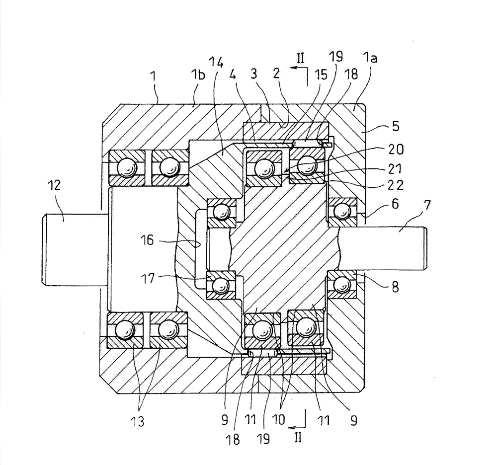
[0074] Embodiments of the present invention will be described below with reference to the drawings. Such as figure 1 As shown, the housing 1 is cylindrical. The housing 1 is divided into two parts in the axial direction, and a first divided housing 1a and a second divided housing 1b are provided.

[0075] The first split case 1a and the second split case 1b are integrally fastened by bolts (not shown), and formed so as to straddle the first split case 1a and the second split case 1b on the inner diameter surface of the end portion on the abutting side. There is a large-diameter concave portion 2 .

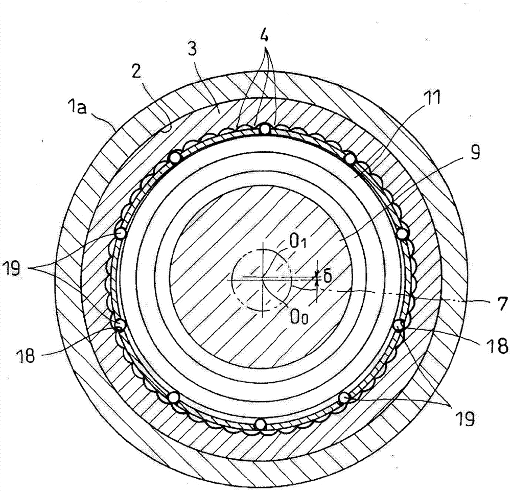
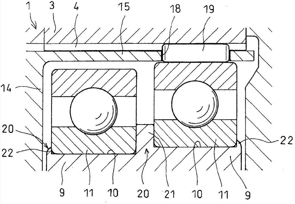
[0076] Such as figure 1 and figure 2 As shown, an internal gear 3 is pressed into the large-diameter concave portion 2 , and a plurality of internal teeth 4 are provided on the inner periphery of the internal gear 3 .

[0077] Such as figure 1 As shown, an end plate 5 is provided at an opening end portion of the first divided case 1a, and an input shaft 7 is inserted into a ...


PUM


Abstract

A reduction device configured in such a manner that roller guiding bearings which are pressure-fitted on the eccentric circular plates of the input shaft is stably installed to suppress a reduction in the efficiency due to the coming out of the bearings. An input shaft (7) is disposed so as to be coaxial with a stationary internal gear (3), two eccentric circular plates (9) which can rotate within the internal gear (3) are provided to the input shaft (7), and roller guiding bearings (11) are pressure-fitted on the respective outer diameter surfaces of the eccentric circular plates (9). A cage (15) which can rotate between the internal gear (3) and the eccentric circular plates (9) is provided to a shaft end section of the output shaft (12) which is disposed coaxially with the input shaft (7). Roller containing pockets (18), the number of which is less than the number of the internal teeth (4) of the internal gear (3), are formed in the cage (15). Rollers (19) are individually received within the roller containing pockets (18). The rotation of the eccentric circular plates (9) which rotate together with the input shaft (7) sequentially engages the rollers (19) with the internal teeth (4). One rotation of the input shaft (7) moves the rollers (19) in the circumferential direction by a distance corresponding to a tooth of the internal teeth (4) to rotate the output shaft (12) at a reduced speed. A circular protrusion (21) is provided between the two eccentric circular plates (9), and staking protrusions (22) are provided at axially opposing ends of the eccentric circular plates (9). The staking protrusions (22) and the annular protrusion (21) prevent the bearing (11) from moving in the axial direction.

Description

technical field [0001] The present invention relates to a roller reduction gear transmission that transmits rotational deceleration of an input shaft to an output shaft by sequentially meshing rollers with a number of internal teeth less than the number of internal teeth of the internal gear with internal teeth formed on the inner circumference of the internal gear. Background technique [0002] As such a reduction gear transmission, a device described in Patent Document 1 is conventionally known. In this roller reduction gear unit, the input shaft and the output shaft are arranged coaxially so that the ends of the shafts face each other, and the outer shell covering the ends of the two shafts has a plurality of curved shafts on the inner circumference. An internal gear with internal teeth is supported, and two eccentric discs capable of rotating inside the internal gear are provided at the shaft end of the input shaft at a distance in the axial direction, and at the shaft e...

Claims


Application Information

Patent Timeline
Patent Type & Authority Applications(China)
IPC IPC(8): F16H1/32F16C19/06F16C33/38F16C33/44F16C33/46F16C33/66F16C35/06
CPCF16H1/32F16C33/4623F16C35/06F16C33/6681F16C33/3875F16C33/44F16C19/06F16C33/6651F16C35/063F16C2226/74
Inventor 佐藤光司秋吉幸治中小路雅文斋藤隆英宇都宫聪
Owner NTN CORP
Why Eureka
Try Eureka