
Casting core-splitting process for Vee cylinder block

A cylinder block and split core technology, applied in the direction of cores, casting mold components, manufacturing tools, etc., can solve the problems of lower core positioning accuracy, difficult core making, and large number of sand cores, etc., to achieve accurate core positioning and reduce The number of sand cores and the effect of simplifying the external structure

Active Publication Date: 2013-05-29
GUANGXI YUCHAI MASCH CO LTD
View PDF6 Cites 11 Cited by
  • Summary
  • Abstract
  • Description
  • Claims
  • Application Information

AI Technical Summary

Problems solved by technology

[0006] (1) The number of sand cores is large, the cost of circulation management is increased, and the efficiency is reduced. When each sand core is assembled, there are many positioning levels, which leads to a decrease in positioning accuracy;
[0007] (2) Divide the core according to the function, the tappet chamber sand core and the waterway sand core will be very long, which will cause them to be easily deformed during the circulation process. If they are divided into several sections, the positioning accuracy of the lower core will decrease, and the separated surface will easily form thick the critics;
[0008] (3) The upper and lower shapes are formed with casting parts, which leads to the complexity of the upper and lower shape molds and increases the mold cost;
[0009] (4) According to this split-core process, some long, thin and low-strength sand cores such as tappet chamber sand cores and channel sand cores will be deformed when pouring molten iron, and will break in severe cases, resulting in castings that do not fit in size and are scrapped;
[0010] (5) According to this kind of core separation process, the mold process of water channel sand core and tappet chamber sand core is complicated and difficult to make core

Method used


Image

  • Casting core-splitting process for Vee cylinder block
  • Casting core-splitting process for Vee cylinder block
  • Casting core-splitting process for Vee cylinder block

Examples


Embodiment Construction

[0031] A specific embodiment of the present invention will be described in detail below in conjunction with the accompanying drawings, but it should be understood that the protection scope of the present invention is not limited by the specific embodiment.

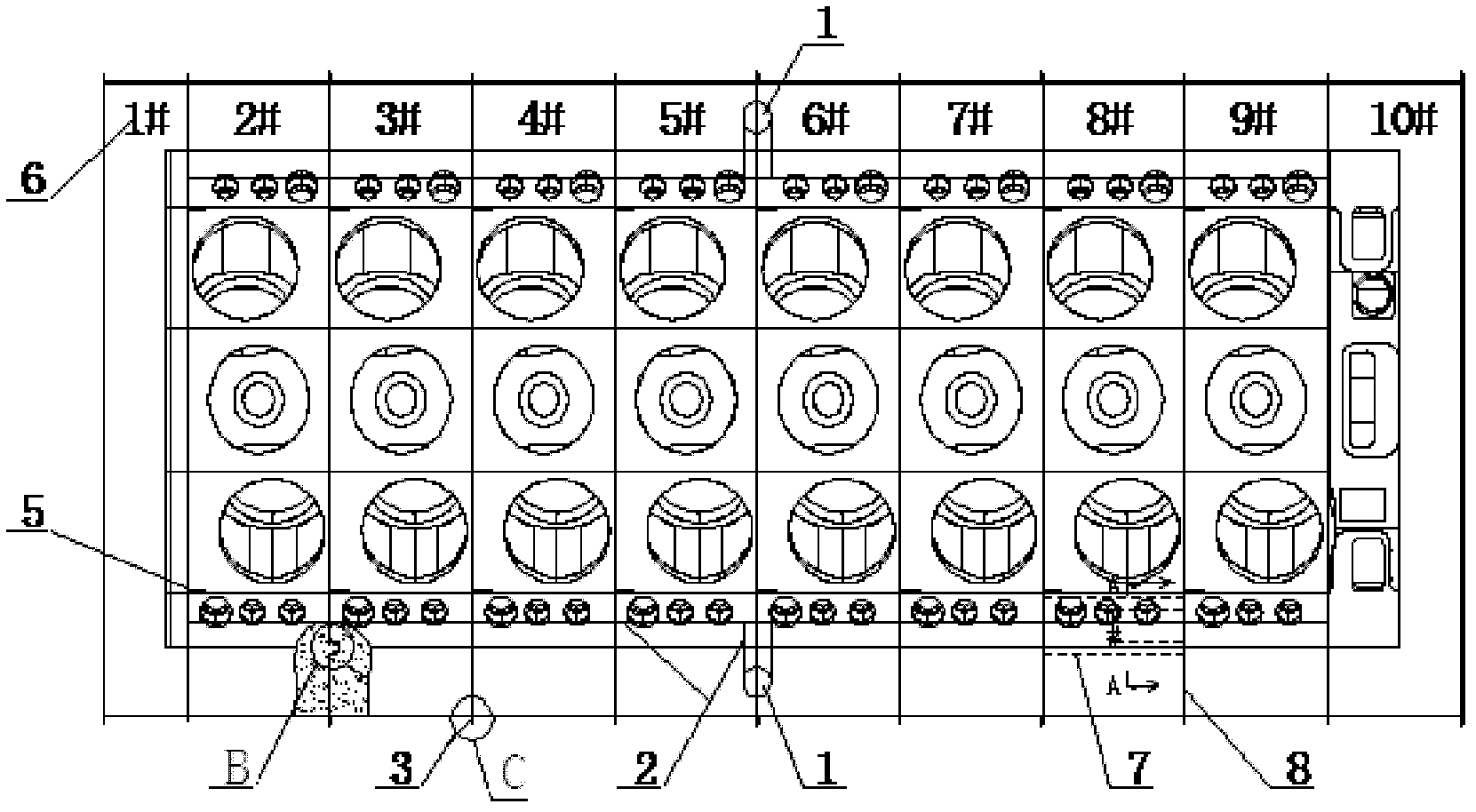
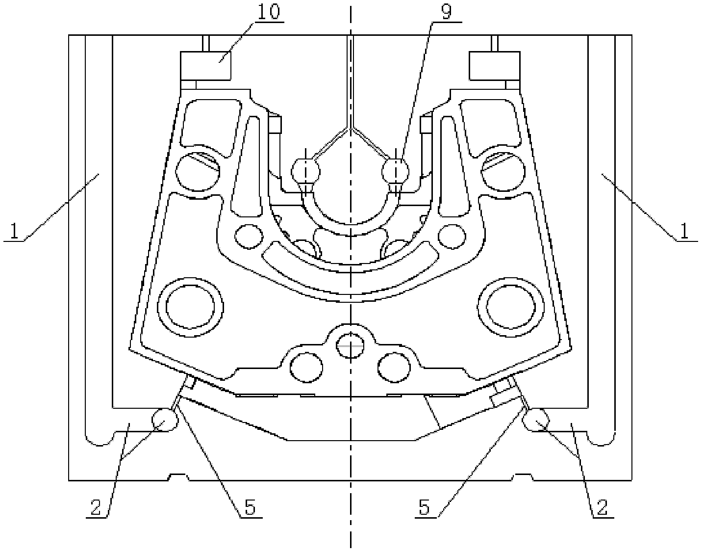
[0032] The V-shaped cylinder block casting split core process adopts the integral surrounding split core, such as Figure 7 As shown, the specific steps include:

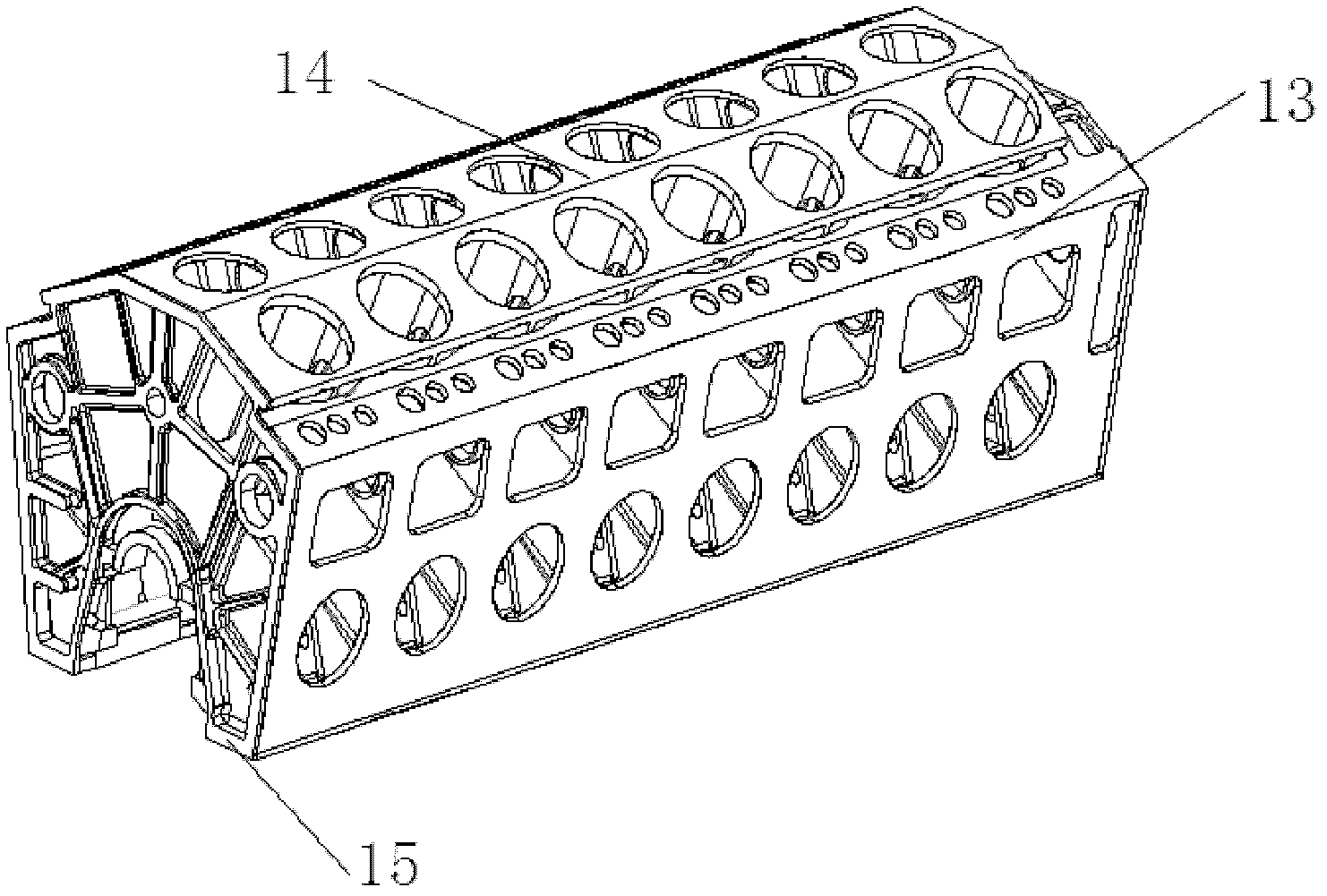
[0033] V-shaped cylinder block 13 (such as figure 1 with figure 2 As shown), the direction of the cylinder top 14 is facing downwards, and the direction of the machine feet 15 is placed upward (upside down). The bottom surface of the sand core is designed with the minimum sand consumption of the cylinder top at 150mm, and the outer side of the sand core is designed with the minimum sand consumption of 200mm on the other sides. , each sand core is divided by the core line 8 to meet the core-making requirements, and the sand cores are separated from the V-shape...


PUM


Abstract

The invention discloses a casting core-splitting process for a Vee cylinder block. Integral enclosing core splitting is applied. The casting core-splitting process for the Vee cylinder block includes the steps of firstly, allowing the top of the Vee cylinder block to face down and legs to face up, and designing the bottom surface and outer side of a sand core; secondly, splitting the whole sand core into a front insert core, a rear insert core and a plurality of main cores between the front insert core and the rear insert core along a splitting line from the front end to the rear end of the Vee cylinder block; and thirdly, designing a universal tapper chamber core on each main core independently. By the integral enclosing splitting manner with the auxiliary core positioning measure, the number of the cores is creased, mould manufacturing process is simplified, appearance structure is simplified, core setting is convenient, positioning in core setting is accurate, core strength is ensured, deformation in turnover and casting process is avoided, productivity is improved, and production cost is saved.

Description

technical field [0001] The invention relates to the field of engines, in particular to a V-shaped cylinder body casting split core process. Background technique [0002] At present, most of the domestic foundry industry, especially the casting of cast iron parts of ship machinery, have developed or are developing V-type engines. [0003] At present, most domestic foundry enterprises adopt the traditional method when producing large V-shaped engine cylinder blocks: that is, the casting process of dividing the core according to the function of the sand core. This casting process divides the sand core into: the lower shape, the left and right tappet chamber sand cores, several waterway sand cores, the main oil passage sand core, several main body sand cores, front-end insert sand cores, and rear-end insert sand cores. Core, left and right side sand cores and upper shape, sometimes in order to arrange the lower gating system, an additional auxiliary sand core is needed. [000...

Claims


Application Information

Patent Timeline
Patent Type & Authority Applications(China)
IPC IPC(8): B22C9/10
Inventor 杨双华廖文东龙善北宁科明
Owner GUANGXI YUCHAI MASCH CO LTD
Learn More