
Steel grating welding machine

A steel grating and welding machine technology, which is applied in welding equipment, auxiliary welding equipment, welding/cutting auxiliary equipment, etc., can solve the problems of difficult product quality assurance, high labor intensity of workers, and low work efficiency, so as to reduce the scrap rate , Reduce labor intensity and improve work efficiency

Active Publication Date: 2015-06-03
NINGBO XINZHOU RESISTANCE WELDER
View PDF7 Cites 3 Cited by
  • Summary
  • Abstract
  • Description
  • Claims
  • Application Information

AI Technical Summary

Problems solved by technology

There are already strict national standards for existing steel gratings. To produce steel gratings that meet the requirements, multiple processes such as feeding, welding, cutting, and transportation are required. Most of the existing steel grating welding machines only include flat steel clamping. Mechanism, welding device and material cutting device, among which the material cutting device is through the way of upper cutter and lower pressure cutting material. Before welding, the cross bar feeding and steel grating conveying are mostly manual operation, which has high labor intensity and low work efficiency. High scrap rate and difficult to guarantee product quality

Method used


Image

  • Steel grating welding machine
  • Steel grating welding machine
  • Steel grating welding machine

Examples


Embodiment Construction

[0020] The present invention will be further described below in conjunction with the accompanying drawings and specific embodiments.

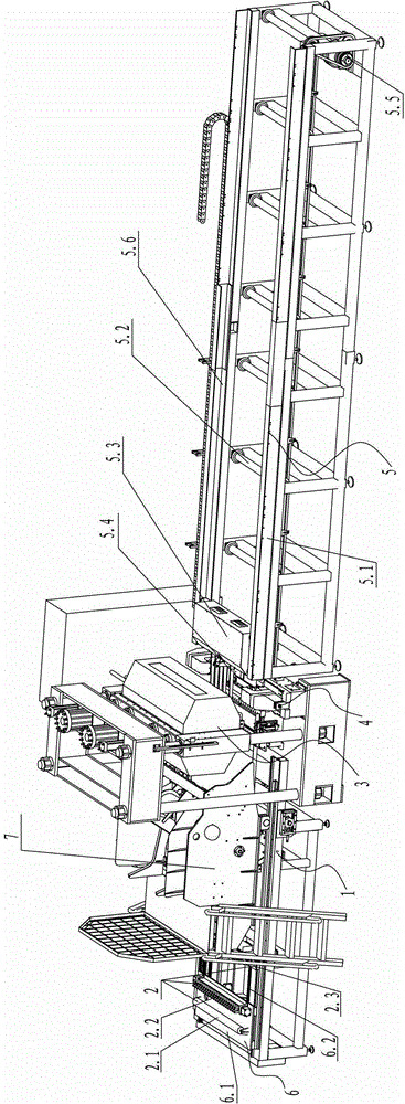
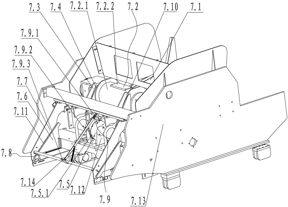
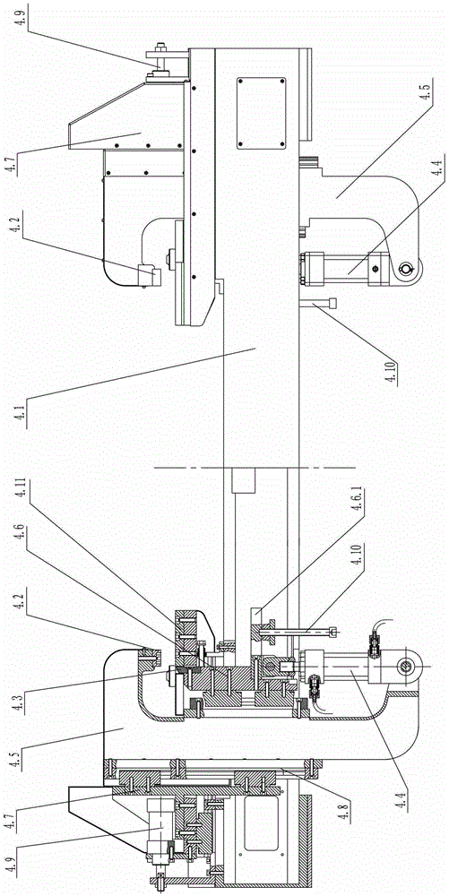
[0021] see Figure 1 to Figure 4 As shown, the steel grating welding machine of the present invention includes a support frame 1, a positioning clamping device 2, a welding device 3 and a cutting device 4, and the cutting device 4 is located behind the welding device 3, and it also includes a feeding device And conveying device 5, described feeding device comprises flat steel feeding device 6 and crossbar feeding device 7, and described flat steel feeding device 6 is arranged on the support frame 1, and described positioning clamping device 2 is arranged on the support frame 1 and Connect with the flat steel feeding device 6, the cross bar feeding device 7 is located on the support frame 1 and is positioned above the flat steel feeding device 6, and the welding device 3 is positioned behind the flat steel feeding device 6 and the cross bar feed...


PUM


Abstract

Disclosed is a steel grating welding machine. The steel grating welding machine comprises a support (1), a positioning and clamping device (2), a welding device (3) and a material-cutting device (4), wherein the material-cutting device (4) is arranged on the back of the welding device (3). The steel grating welding machine is characterized by further comprising a feeding device and a conveying device (5), wherein the feeding device comprises a flat steel feeding device (6) and a cross rod feeding device (7), the flat steel feeding device (6) is arranged on the support (1), the positioning and clamping device is arranged on the support (1) and is connected with the flat steel feeding device (6), the cross rod feeding device (7) is arranged on the support (1) and is arranged above the flat steel feeding device (6), the welding device (3) is arranged on the back of the flat steel feeding device (6) and the cross rod feeding device (7), and the conveying device (5) is connected on the back of the material-cutting device (4). The steel grating welding machine can reduce labor intensity, improve work efficiency, reduce rejection rate, and improve product quality.

Description

technical field [0001] The invention relates to a welding machine, in particular to a steel grating welding machine. Background technique [0002] Steel grating is a kind of steel product that is cross-arranged with flat steel according to a certain spacing and cross bars, and welded into a square grid in the middle. Steel grating is mainly used as ditch cover plate, steel structure platform plate, steel Ladder treads, etc. There are already strict national standards for existing steel gratings. To produce steel gratings that meet the requirements, multiple processes such as feeding, welding, cutting, and transportation are required. Most of the existing steel grating welding machines only include flat steel clamping. Mechanism, welding device and material cutting device, wherein the material cutting device is through the way of upper cutter and lower pressure cutting material. Before welding, the cross bar feeding and steel grating conveying are mostly manual operation, wh...

Claims


Application Information

Patent Timeline
Patent Type & Authority Patents(China)
IPC IPC(8): B23P23/02B23Q7/14B23Q7/05B23K37/04B23D15/14
Inventor 陈增光
Owner NINGBO XINZHOU RESISTANCE WELDER
Learn More