Milling groove clamping device of sleeve-class part

A clamping device and parts technology, applied in the field of milling and clamping devices, can solve the problems of low production efficiency and high labor intensity of workers, and achieve the effects of high clamping quality, reduced labor intensity of workers, and stable clamping force.

Active Publication Date: 2013-05-29
佛山市顺德区上锐机械有限公司
View PDF6 Cites 1 Cited by
  • Summary
  • Abstract
  • Description
  • Claims
  • Application Information

AI Technical Summary

Problems solved by technology

In the above-mentioned processing process, the positioning and clamping of parts need to be done manually by the operator, which leads to low production efficiency and high labor intensity for workers.

Method used


Image

  • Milling groove clamping device of sleeve-class part
  • Milling groove clamping device of sleeve-class part
  • Milling groove clamping device of sleeve-class part

Examples


Embodiment Construction

[0018] The present invention will be described in further detail below in conjunction with the accompanying drawings and embodiments.

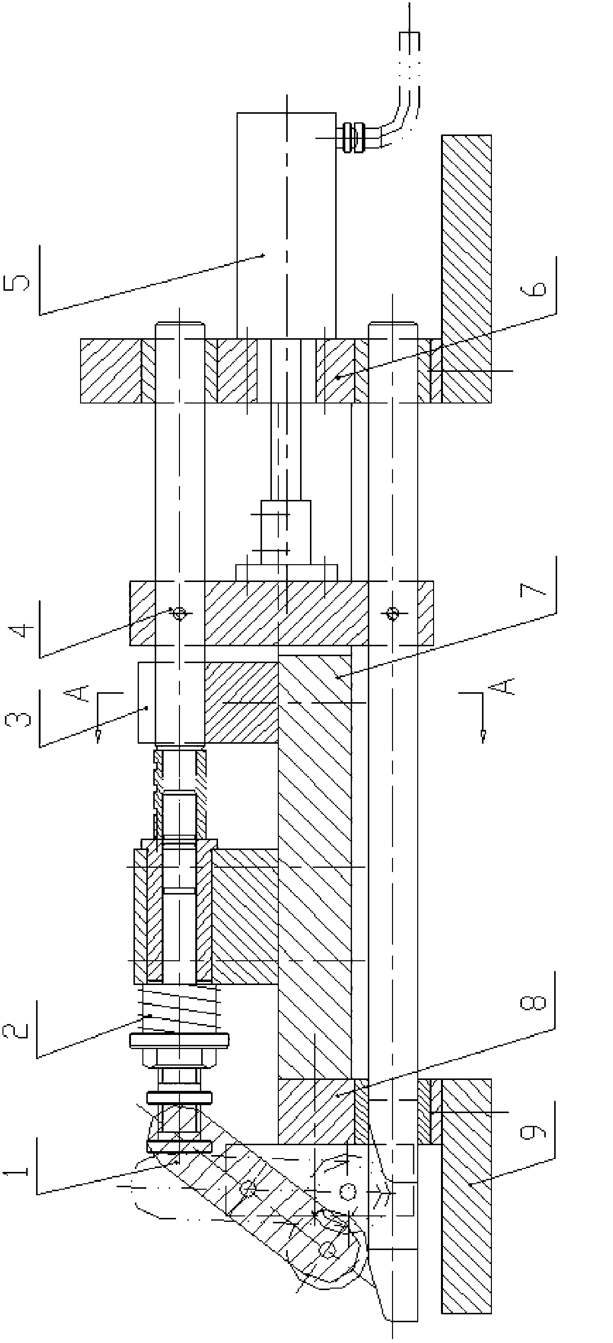
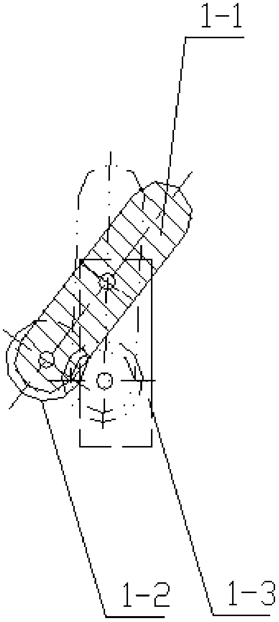
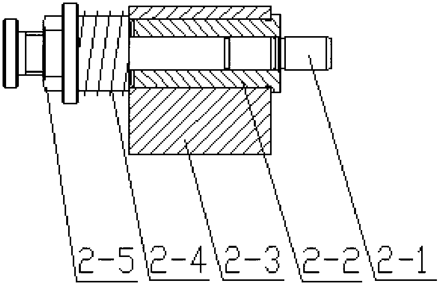
[0019] Such as Figure 1~Figure 3 with Figure 5~Figure 7 As shown, a milling and clamping device for sleeve parts includes a fixed seat 9, a left vertical plate 8 and a right vertical plate 6 fixedly connected to the fixed seat 9, fixedly connected to the left vertical plate 8 and the The horizontal support plate 7 between the right vertical board 6, the cylinder 5 fixedly connected to the right vertical board 6, the double push rod mechanism 4 connected to the piston of the cylinder 5, and the double push rod mechanism 4 hinged on the left vertical board 8 The force transmission mechanism 1 on the top, the positioning mechanism 2 on the right side of the force transmission mechanism 1 fixed on the horizontal support plate 7 and the automatic loading and unloading mechanism 3 arranged on the right side of the positioning mechanism 2; The pu...


PUM


Abstract

The invention relates to a milling fixture, in particular to a milling groove clamping device of a sleeve-class part. The milling groove clamping device of the sleeve-class part comprises a fixed base, a left vertical plate and a right vertical plate, wherein the left vertical plate and the right vertical plate are fixedly connected on the fixed base, a horizontal supporting plate fixedly connected between the left vertical plate and the right vertical plate, an air cylinder fixedly connected on the right vertical plate, a double-pushrod mechanism connected on a piston of the air cylinder, a power transmission mechanism hinged on the left vertical plate, a positioning mechanism fixedly connected on the horizontal supporting plate and an automatic feeding and discharging mechanism arranged on the right side of the positioning mechanism. By adopting the technical scheme, the machining accuracy requirement of the part can be guaranteed, clamping force is stable, clamping quality is high, the speediness and automation of the clamping of the part are achieved, production efficiency is improved greatly and working intensity of workers is relieved greatly.

Description

technical field [0001] The invention relates to a milling fixture, in particular to a slot milling and clamping device for sleeve parts. Background technique [0002] There is a kind of shaft sleeve parts on textile machinery equipment, the production quantity is large, and it is necessary to use Figure 8 The special milling fixture shown in the figure clamps the parts. The main processing steps are internal and external circle and end surface processing, and groove processing. The groove is processed on a general-purpose milling machine, so as to ensure the requirements of processing accuracy. In the above-mentioned processing process, the positioning and clamping of the parts need to be done manually by the operator, which leads to low production efficiency and high labor intensity for workers. Contents of the invention [0003] The object of the present invention is to provide a clamping device for realizing automatic positioning and clamping of groove milling processi...

Claims


Application Information

Patent Timeline
IPC IPC(8): B23Q7/08
Inventor 苏宝莉顾惠斌刘贤锋陈俊
Owner 佛山市顺德区上锐机械有限公司
Why Eureka
Try Eureka