
Valve core forming and cutting process and integrated mold

A molding die and spool technology, applied in metal processing, etc., can solve problems such as non-standard spool cuts, complicated process, and low production efficiency, and achieve the effects of improving product qualification rate, reducing professionals, and improving production efficiency

Active Publication Date: 2016-04-27
厦门市金汤橡塑有限公司
View PDF9 Cites 0 Cited by
  • Summary
  • Abstract
  • Description
  • Claims
  • Application Information

AI Technical Summary

Problems solved by technology

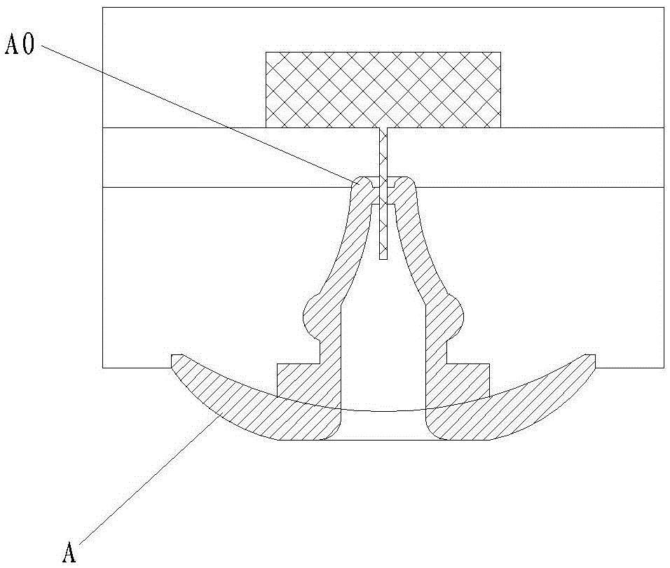
[0002] The spool A in the carburetor (carburettor) is an important part. The existing spool products are molded through a mold, and then vulcanized and demoulded. After cooling, a single incision or cutting operation is performed manually. low yield
The applicant's previous patent document CN200810071870.2 discloses a carburetor valve core production process and a special mold, which realizes the problem of one-time incision of the whole mold. However, the valve core forming and incision in the document are made of two sets of molds: first It is formed by a set of molds, and the product is taken out and cut by another mold. The process is more complicated, resulting in low production efficiency; in addition, the cutter in the literature is penetrated by the small end surface A0 of the valve core, which is prone to deviation and occurrence of accidents. Taste

Method used


Image

  • Valve core forming and cutting process and integrated mold
  • Valve core forming and cutting process and integrated mold
  • Valve core forming and cutting process and integrated mold

Examples


Embodiment

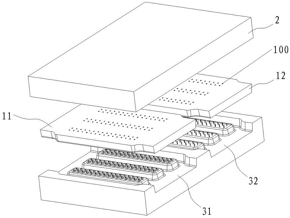
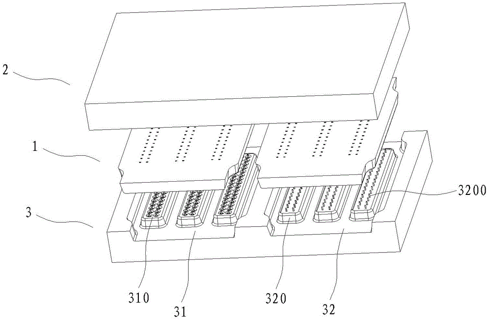
[0024] Example: see Figure 2 to Figure 4 , a valve core forming and cutting integrated mold, including an upper die 1, an upper template 2 and a lower die 3, wherein the upper die 1 is composed of two independent forming dies 11 and a notch die 12, the forming die 11 and the notch The mold 12 is movably installed on the upper template 2 through the positioning guide pillars; the lower mold 3 is provided with a molding area 31 and a notch area 32, and cooperates with the forming mold 11 and the notch mold 12 of the upper mold to form several valve core cavities and notches Cavities are provided with through holes 100 on the top surface of each cavity of the forming die 11 and the notch die 12, and the notch area 32 of the lower die is provided with a cutter 3200 that cooperates with each notch cavity, and each cutter 3200 is cut from the spool The inner hole at the big end penetrates and extends to the upper template. The molding area of ​​the lower mold 3 of the present inve...


PUM


Abstract

The invention discloses valve core forming and cutting technology and an integral die. Forming operation is carried out on a forming part of a die when dies are compounded, cutting operation is carried out on a cut part of the die at the same time, and each cutter of the cut part penetrates through a big end of a valve core. Vulcanization forming and whole die standard cutting of a product are carried out at the same time when the integral die is produced, so that the integral die has the advantages of being consistent in cutting standard, normative in operation, high in production efficiency, stable in valve core quality and the like.

Description

technical field [0001] The invention discloses a valve core forming and cutting process and an integrated mold, which belong to the technical field of carburetor valve core manufacturing according to the International Patent Classification (IPC). Background technique [0002] The spool A in the carburetor (carburettor) is an important part. The existing spool products are molded through a mold, and then vulcanized and demoulded. After cooling, a single incision or cutting operation is performed manually. The yield rate is low. The applicant's previous patent document CN200810071870.2 discloses a carburetor valve core production process and a special mold, which realizes the problem of one-time incision of the whole mold. However, the valve core forming and incision in the document are made of two sets of molds: first It is formed by a set of molds, and the product is taken out and cut by another mold. The process is more complicated, resulting in low production efficiency; ...

Claims


Application Information

Patent Timeline
Patent Type & Authority Patents(China)
IPC IPC(8): B26F1/44B29C35/02B29C33/00
Inventor 何龙河
Owner 厦门市金汤橡塑有限公司
Learn More