
Rotary buncher

A concentrator and rotary technology, applied in glass manufacturing equipment, manufacturing tools, etc., can solve the problems of increasing the tension of the original fiber tow, generating filaments, and wearing the concentrator wheel, so as to prolong the service life, reduce the splitting, avoid the The effect of local wear

Inactive Publication Date: 2013-05-29
GUANGZHOU ZHONGXIN CENTURY FIBERGLASS
View PDF3 Cites 4 Cited by
  • Summary
  • Abstract
  • Description
  • Claims
  • Application Information

AI Technical Summary

Problems solved by technology

[0002] Glass fiber is now mostly manufactured through the drawing process of the pool kiln. Various raw materials are mixed evenly in different proportions and sent to the pool kiln to be melted into molten glass. After clarification, the molten glass flows into the platinum-rhodium alloy drain plate on the branch road. A lot of small holes are formed, and the glass is pulled out from these small holes by a wire drawing machine to form glass fibers. The above-mentioned glass fiber drawing method produces dispersed glass fiber monofilaments, which are coated with sizing agent through an oiler. Finally, a bundle is integrated through the bundle wheel, and finally wound on the winding drum. Most of the bundle wheels in the prior art are fixed bundle wheels. The local wear of the cluster wheel is serious, and the tension of the original filament bundle is increased and hairs are generated in the subsequent processing process, which affects the quality of glass products

Method used


Image

  • Rotary buncher

Examples


Embodiment Construction

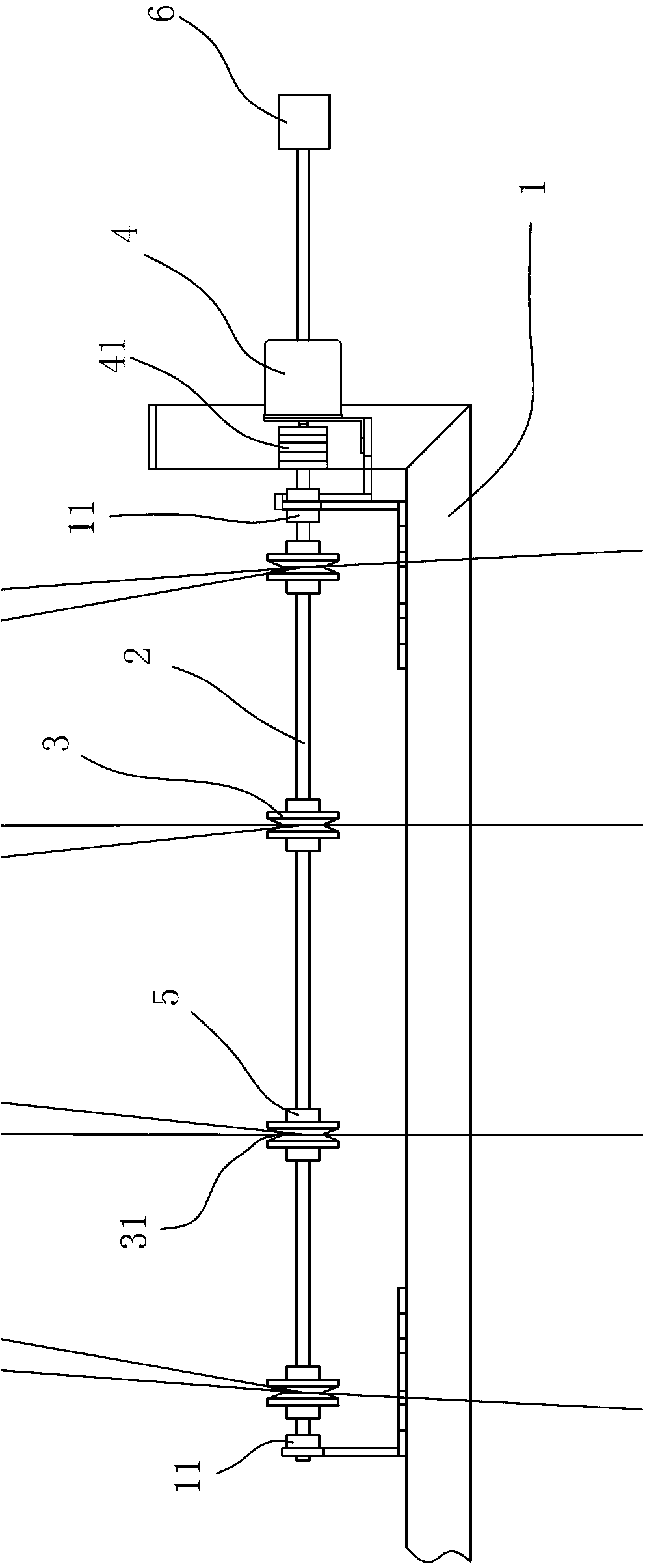
[0012] refer to figure 1 , a kind of rotary buncher of the present invention, comprises support 1, the bunching shaft 2 that is arranged on the bracket 1, and several bunching wheels 3 that are arranged on the bunching shaft 2, is also provided with motor 4 on the bracket 1, and motor 4 and bunching The shaft 2 is connected by transmission, and the motor 4 is also connected with an intermediate relay 6 .

[0013] The rotary clusterer is provided with a motor 4 and an intermediate relay 6 connected to the cluster shaft 2, and the control signal is connected to the intermediate relay 6 to control the rotation of the motor 4, so that the cluster wheel 3 on the cluster shaft 2 is driven by the motor 4 Rotate slowly and periodically. During the periodical rotation of the cluster wheel 3, the part where the tow is in contact with the cluster wheel 3 is not limited to one place on the cluster wheel 3, but multiple places are in contact with the cluster wheel 3 periodically. , so as ...


PUM


Abstract

The invention discloses a rotary buncher comprising a bracket, a bunching shaft arranged on the bracket and a plurality of bunching wheels arranged on the bunching shaft. A motor is further arranged on the bracket and is in transmission connection with the bunching shaft; the motor is further connected with an intermediate relay; and the rotary buncher controls the connection of signals into the intermediate relay so as to control the rotation of the motor through the motor and the intermediate relay which are in transmission connection with the bunching shaft, so that the bunching wheels on the bunching shaft slowly and periodically rotates under the driving of the motor, and tows periodically contact the bunching wheels at a plurality of places instead of at one place on the bunching wheels during the periodic rotation of the bunching wheels, so that partial abrasion of the bunching wheels is avoided, the service lives of the bunching wheels are prolonged, and simultaneously the precursor fiber tow splitting is reduced. The rotary buncher is used in the field of fiberglass bunchers.

Description

technical field [0001] The invention relates to the technical field of glass fiber manufacturing, in particular to a glass fiber bundler. Background technique [0002] Glass fiber is now mostly manufactured through the drawing process of the pool kiln. Various raw materials are mixed evenly in different proportions and sent to the pool kiln to be melted into molten glass. After clarification, the molten glass flows into the platinum-rhodium alloy drain plate on the branch road. A lot of small holes are formed, and the glass is pulled out from these small holes by a wire drawing machine to form glass fibers. The above-mentioned glass fiber drawing method produces dispersed glass fiber monofilaments, which are coated with sizing agent through an oiler. Finally, a bundle is integrated through the bundle wheel, and finally wound on the winding drum. Most of the bundle wheels in the prior art are fixed bundle wheels. The local wear of the cluster wheel is serious, and the tensio...

Claims


Application Information

Patent Timeline
Patent Type & Authority Applications(China)
IPC IPC(8): C03B37/10
Inventor 董结初伍伟强白琼林
Owner GUANGZHOU ZHONGXIN CENTURY FIBERGLASS
Learn More