Intelligent lamplight control system

A control system, intelligent lighting technology, applied in the direction of energy-saving control technology, light source, electric light source, etc., can solve the problems of reducing the working life of electrical equipment, burning electronic equipment, crashes, etc., to avoid damage to the control circuit, ensure safe work, Good effect of surge protection function

Active Publication Date: 2013-05-29
STATE GRID SHANXI ELECTRIC POWER COMPANY CHANGZHIELECTRIC POWER SUPPLY +1
View PDF3 Cites 7 Cited by
  • Summary
  • Abstract
  • Description
  • Claims
  • Application Information

AI Technical Summary

Problems solved by technology

[0002] In the currently used lighting control device, when the heavy equipment under the same transformer or the same line is short-circuited or the power is switched, the power supply is very easy to generate and output surge voltage or surge current. This instantaneous pulse energy will impact the control circuit. Reduce the working life of electrical equipment, and burn the electronic equipment in serious cases; on the other hand, the traditional lighting control circuit uses transistors to directly drive the relay coil on the lamp circuit, and the reverse pulse voltage will be generated when the coil on the lamp circuit discharges Shock the transistor, reduce the service life of the transistor, or even break it down, making the circuit control invalid. At the same time, the signal input and output terminals of the single-chip microcomputer will also be impacted by the pulse voltage due to the damage of the transistor, which will damage the single-chip microcomputer chip, which may cause the single-chip microcomputer to reset and crash. , flying or control errors and other issues

Method used


Image

  • Intelligent lamplight control system
  • Intelligent lamplight control system
  • Intelligent lamplight control system

Examples


Embodiment Construction

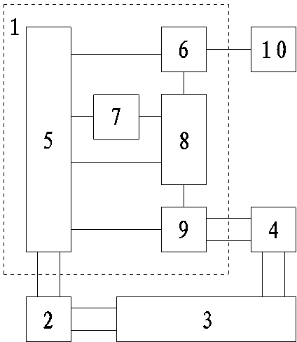
[0034] Such as Figure 1 to Figure 4 As shown, the intelligent lighting control system of the present invention includes: a host control unit 1, a control box power supply 2, a mains power supply 3 and a lighting module 4; the host control unit 1 includes: a power protection module 5, a data communication module 6, a clock A control module 7, a microcontroller 8 and a relay light control module 9, the power protection module 5 is respectively connected to the data communication module 6, the clock control module 7, the microcontroller 8 and the relay light control module 9;

[0035] The signal input terminal of the microcontroller 8 is connected to the clock control module 7, the data communication terminal of the microcontroller 8 is connected to the data communication module 6, and the signal output terminal of the microcontroller 8 is connected to the relay light control module 9;

[0036] The power output ends of the mains power supply 3 are respectively connected to the c...


PUM


Abstract

The invention relates to an intelligent lamplight control system and belongs to the technical field of intelligent lamplight control devices. The intelligent lamplight control system can prevent power supply surge pulses from damaging a lamp control deivce and can prevent discharging pulses of a relay coil from damaging the lamp control device. The technical scheme is that a power supply protection module is respectively connected with a data communication module, a time clock control module, a microcontroller and a relay lamp control module. The signal input end of the microcontroller is connected with the time clock module, the data communication end of the microcontroller is connected with the data communication module, and the signal output end of the microcontroller is connected with the relay lamp control module. The power supply output end of a mains supply is respectively connected with a control box power supply and a lamplight module. The intelligent lamplight control system can be installed in the lamp control device to be used.

Description

technical field [0001] The intelligent lighting control system of the invention belongs to the technical field of intelligent lighting control equipment. Background technique [0002] In the current lighting control device, when the heavy equipment under the same transformer or the same line is short-circuited or the power is switched, the power supply is very likely to generate and output surge voltage or surge current. This instantaneous pulse energy will impact the control circuit. Reduce the working life of electrical equipment, and burn electronic equipment in severe cases; on the other hand, in traditional lighting control circuits, transistors are used to directly drive the relay coil on the lamp circuit, and the reverse pulse voltage will be generated when the coil on the lamp circuit discharges Shock the transistor, reduce the service life of the transistor, or even break it down, making the circuit control invalid. At the same time, the signal input and output term...

Claims


Application Information

Patent Timeline
IPC IPC(8): H05B37/02H02H9/04H02H9/06
CPCY02B20/48Y02B20/42Y02B20/40
Inventor 申庆斌杨波王晓东杨军
Owner STATE GRID SHANXI ELECTRIC POWER COMPANY CHANGZHIELECTRIC POWER SUPPLY
Why Eureka
Try Eureka