AI technical title is built by Patsnap AI team. It summarizes the technical point description of the patent document.
A control system and intelligent lighting technology, applied in energy-saving control technology, light source, electric light source, etc., can solve problems such as crash, reduce the working life of electrical equipment, burn out electronic equipment, etc., achieve good surge protection function, avoid damage control circuit, to ensure the effect of safe work
Active Publication Date: 2015-09-16
STATE GRID SHANXI ELECTRIC POWER COMPANY CHANGZHIELECTRIC POWER SUPPLY +1
View PDF3 Cites 0 Cited by
Summary
Abstract
Description
Claims
Application Information
AI Technical Summary
This helps you quickly interpret patents by identifying the three key elements:
Problems solved by technology
Method used
Benefits of technology
Problems solved by technology
[0002] In the currently used lighting control device, when the heavy equipment under the same transformer or the same line is short-circuited or the power is switched, the power supply is very easy to generate and output surge voltage or surge current. This instantaneous pulse energy will impact the control circuit. Reduce the working life of electrical equipment, and burn the electronic equipment in serious cases; on the other hand, the traditional lighting control circuit uses transistors to directly drive the relay coil on the lamp circuit, and the reverse pulse voltage will be generated when the coil on the lamp circuit discharges Shock the transistor, reduce the service life of the transistor, or even break it down, making the circuit control invalid. At the same time, the signal input and output terminals of the single-chipmicrocomputer will also be impacted by the pulse voltage due to the damage of the transistor, which will damage the single-chipmicrocomputerchip, which may cause the single-chip microcomputer to reset and crash. , flying or control errors and other issues
Method used
Image
Click on the blue label to locate the original text in one second.
Reading with bidirectional positioning of images and text.
Examples
Embodiment Construction
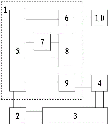
[0035] Such as Figure 1 to Figure 4 所示,本发明智能灯光控制系统,包括:主机控制单元1、控制箱电源2、市电电源3和灯光模块4;所述主机控制单元1包括:电源保护模块5、数据通讯模块6、时钟控制模块7、微控制器8和继电器灯控模块9,所述电源保护模块5分别与数据通讯模块6、时钟控制模块7、微控制器8和继电器灯控模块9相连;
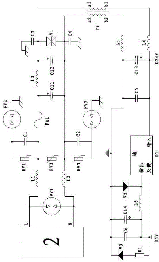
[0042]The other end of the fuse FA1 is connected in parallel with the positive pole of the polar capacitor C11 and then connected with one end of the inductor L3, and the other end of the inductor L3 is sequentially connected in parallel with the positive pole of the polar capacitor C12...
PUM
Abstract
The invention relates to an intelligent lamplight control system and belongs to the technical field of intelligent lamplight control devices. The intelligent lamplight control system can prevent power supply surge pulses from damaging a lamp control deivce and can prevent discharging pulses of a relay coil from damaging the lamp control device. The technical scheme is that a power supply protection module is respectively connected with a data communication module, a time clock control module, a microcontroller and a relay lamp control module. The signal input end of the microcontroller is connected with the time clock module, the data communication end of the microcontroller is connected with the data communication module, and the signal output end of the microcontroller is connected with the relay lamp control module. The power supply output end of a mains supply is respectively connected with a control box power supply and a lamplight module. The intelligent lamplight control system can be installed in the lamp control device to be used.
Description
technical field [0001] 本发明智能灯光控制系统,属于智能灯光控制设备技术领域。 Background technique [0002] 当前使用的灯光控制装置,在同一变压器下或者同一线路下的重型设备出现短路或切换电源时,供电电源极易产生并输出浪涌电压或者浪涌电流,这种瞬间脉冲能量会冲击控制电路,降低用电设备的工作寿命,严重时可烧毁电子设备;另一方面,传统灯光控制电路中使用晶体管直接驱动电灯回路上的继电器线圈,当电灯回路上的线圈放电时会产生的反向脉冲电压冲击晶体管,降低晶体管的使用寿命,甚至将其击穿,使电路控制失效,同时单片机的信号输入输出端也会由于晶体管的损坏而受到脉冲电压的冲击,损坏单片机芯片,可能造成单片机复位、死机、跑飞或控制错误等问题。 Contents of the invention [0003] 本发明克服现有技术存在的不足,所要解决的技术问题是:提供一种既能防止电源浪涌脉冲损坏灯控装置,又能防止继电器线圈的放电脉冲损坏灯控装置的智能灯光控制系统。 [0004] 为解决上述问题,本发明所采用的技术方案是:智能灯光控制系统,包括:主机控制单元、控制箱电源、市电电源和灯光模块;所述主机控制单元包括:电源保护模块、数据通讯模块、时钟控制模块、微控制器和继电器灯控模块,所述电源保护模块分别与数据通讯模块、时钟控制模块、微控制器和继电器灯控模块相连; [0005] 所述微控制器的信号输入端与时钟控制模块相连,微控制器的数据通讯端与数据通讯模块相连,微控制器的信号输出端与继电器灯控模块相连; [0006] 所述市电电源的电源输出端分别与控制箱电源和灯光模块相连; [0007] 所述控制箱电源的电源输出端与电源保护模块相连,继电器灯控模块的信号输出端与灯光模块的输入端相连; [0008] 所述电源保护模块的电路结构为:控制箱电源的火线端并接气体放电管FV1的一端后与滤波磁珠L1的一端相连,控制箱电源的零线端并接气体放电管FV1的另一端后与滤波磁珠L2的一端相连; [0009] 所述滤波磁珠L1的另一端依次并接压敏电阻RV1的一端、电容C1的一端后与保险丝FA1的一端相连,所述压敏电阻RV1的另一端并接电容C1的另一端后与气体放电管FV2的一端相连,所述气体放电管FV2的另一端接...
Claims
Application Information
Patent Timeline
Application Date:The date an application was filed.
Publication Date:The date a patent or application was officially published.
First Publication Date:The earliest publication date of a patent with the same application number.
Issue Date:Publication date of the patent grant document.
PCT Entry Date:The Entry date of PCT National Phase.
Estimated Expiry Date:The statutory expiry date of a patent right according to the Patent Law, and it is the longest term of protection that the patent right can achieve without the termination of the patent right due to other reasons(Term extension factor has been taken into account ).
Invalid Date:Actual expiry date is based on effective date or publication date of legal transaction data of invalid patent.
Patent Type & AuthorityPatents(China)
IPC IPC(8): H05B37/02H02H9/04H02H9/06
CPCY02B20/42Y02B20/48Y02B20/40
Inventor申庆斌杨波王晓东杨军
OwnerSTATE GRID SHANXI ELECTRIC POWER COMPANY CHANGZHIELECTRIC POWER SUPPLY

