Double-aerosol-extinguishant spraying device

A spraying device and fire extinguishing agent technology, which is applied in fire rescue and other fields, can solve the problems of small fire extinguishing agent flow rate, inability to realize large flow injection, easy flame re-ignition, etc., and achieve the effect of improving fire extinguishing efficiency

Active Publication Date: 2014-12-31
SHANDONG GUOTAI TECH
View PDF5 Cites 0 Cited by
  • Summary
  • Abstract
  • Description
  • Claims
  • Application Information

AI Technical Summary

Problems solved by technology

These defectives are: water jet fire engine forms a connection line of water jet from the outlet of spray gun (cannon) to fire source, extinguishes the fire with the mode of water jet impact cooling fire source, and this mode of spraying fire extinguishing agent with " point to point " is " One-dimensional injection pattern of fire extinguishing agent", which improves the ability to suppress Class A fires
Although gaseous fire extinguishing agents such as carbon dioxide and heptafluoropropane have "full flooding" fire extinguishing performance, they cannot achieve large-flow injection
However, the disadvantage of the solid-based aerosol fire extinguishing agent is that when its concentration drops, the extinguished flame is easy to re-ignite under the action of residual heat.
201210344566.7 patented technology solves the method of spraying double fire extinguishing agents in the same fire extinguishing agent spray gun at the same time, which is a big step forward in overcoming the problem of easy flame re-ignition, but only one of the double fire extinguishing agents sprayed out can It produces "full submersion" fire extinguishing effect, and there is the problem that the flow rate of the gun (cannon) spraying fire extinguishing agent is small and the injection power is insufficient; the patented technology of 200910035880.5 solves the method of generating air foam fire extinguishing agent in the high-speed airflow of high-power injection, but Cannot generate "total flood" type jets of extinguishing agent that fill the interior of the building

Method used


Image

  • Double-aerosol-extinguishant spraying device
  • Double-aerosol-extinguishant spraying device
  • Double-aerosol-extinguishant spraying device

Examples


Embodiment 1

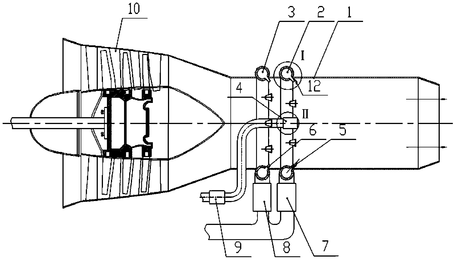
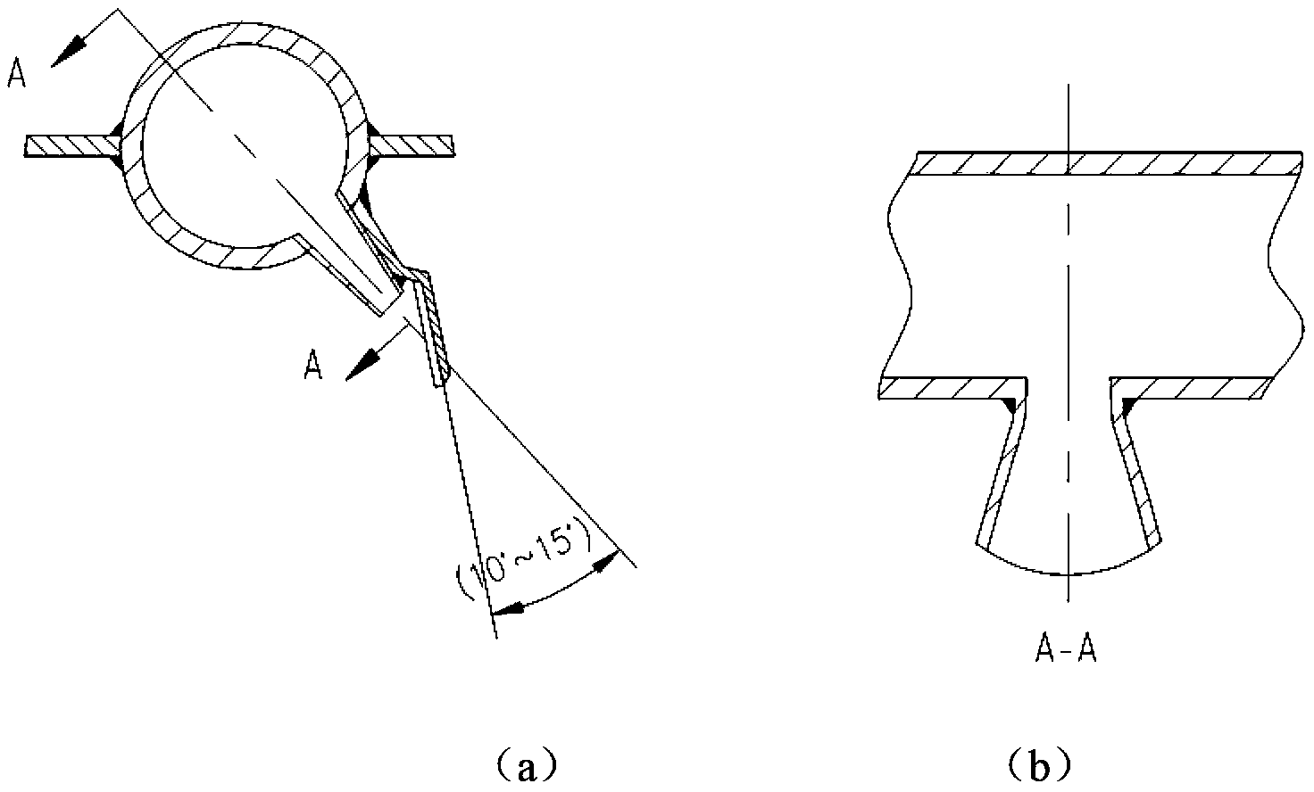
[0021] see figure 1 , image 3 , Figure 4 , when extinguishing the building fire, start the high-speed fan 10, and the high-speed fan 10 will generate a flow of 20-50 m 3 The high-speed gas jet flow of / s enters the aerosol fire extinguishing agent injection cylinder 1, and the injection speed from the nozzle to the outside of the machine is 100-200 m / s. Open the first electromagnetic valve 7 at the lower end of the water transfer ring 2, and the water supplied by the fire truck with a pressure of 0.8-1.0 Mpa and a flow rate of 10-30 kg / s passes through 8 to 16 superfine water outlets on the water transfer ring 2. The mist nozzle 5 shoots ultra-thin high-velocity water jets, and the water jets hit the arc-shaped reflector 12 at an angle of 10° to 15° to sputter into ultra-fine water mist, and form water-based air under the impact of high-speed airflow. Sol fire extinguishing agent jet. The nozzle of the aerosol fire extinguishing agent spray tube 1 is aimed at the opened ...

Embodiment 2

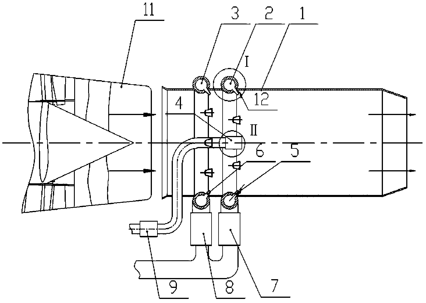
[0023] see figure 2 , image 3 , when used to extinguish fires in petrochemical plants, aircraft, etc., the aviation gas turbine 11 is usually used as the injection power of the gas jet, and the aviation gas turbine 11 is started to generate a flow rate of 20 to 50 m 3 / s gas jet, the wind speed at the outlet is 300-500 m / s. Open the second electromagnetic valve 8 at the lower end of the foam fire extinguishing agent circle 3, and the water film-forming foam fire extinguishing fluid or Class A foam fire extinguishing fluid supplied by the fire truck with a pressure of 0.8-1.0 Mpa and a flow rate of 40-80 kg / s, after 6 to 10 foam fire extinguishing agent nozzles 6 on the foam fire extinguishing agent delivery ring 3 are injected into the aerosol fire extinguishing agent injection cylinder 1 to form an air foam fire extinguishing agent jet, which is mixed with the high-speed airflow and accelerated and sprayed at the fire source. Open the electromagnetic valve 9, and the supe...

Embodiment 3

[0026] see figure 1 , image 3 When it is used for emergency rescue to blow off toxic, harmful, flammable and explosive gases leaked from dangerous chemical transport vehicles or gas pipelines, the high-speed blower fan 10 is parked along the wind direction. Start the high-speed fan 10 or the aviation gas turbine 11 to generate a flow of 20 to 50 m 3 / s, a high-speed gas jet with a flow rate of 100-500 m / s, to blow off or dilute the toxic, harmful, flammable and explosive gases leaked from dangerous chemical transport vehicles or gas pipelines; when the leaked toxic and harmful gases are vulcanized When hydrogen, chlorine, ammonia and other gases are easily soluble in water, open the electromagnetic valve 7 at the lower end of the water transfer ring 2, and the water supplied by the fire truck with a pressure of 0.8-1.0 Mpa and a flow rate of 10-40 kg / s will 8 to 16 ultra-fine water mist nozzles 5 on the water transfer circle 2 are injected into the aerosol fire extinguishin...


PUM


Abstract

The invention discloses a double-aerosol-extinguishant spraying device which comprises a high-shooting-speed fan or an aero-gas turbine, an aerosol extinguishant spraying tube, a water supply ring, a foamite supply ring, a superfine dry powder extinguishing agent spraying gun, a superfine water mist spraying nozzle, a foamite spraying nozzle, a first solenoid valve, a second solenoid valve and a third solenoid valve. The double-aerosol-extinguishant spraying device achieves mass flow and high-shooting-speed spraying. Double-aerosol-extinguishant jet flow sprayed by the double-aerosol-extinguishant spraying device is sprayed into an internal space of a building on fire, aerosol extinguishants are rapidly dispersed to generate a 'totally flooding' state and enter the interior of flames under the action of entrainment airflow of the flames, and consequently a fire in the building can be rapidly put out, and the flames are prevented from reburning.

Description

technical field [0001] The invention belongs to the technical field of fire protection, in particular to a double aerosol fire extinguishing agent injection device. Background technique [0002] From the beginning of the last century to the end of the 1920s, water jet fire trucks, foam fire trucks, and dry powder fire trucks appeared successively in the world. It plays an important role and is the main fire fighting equipment in the current fire fighting. But in the actual combat of fire fighting, it also exposes its technical defects. These defectives are: water jet fire engine forms a connection line of water jet from the outlet of spray gun (cannon) to fire source, extinguishes the fire with the mode of water jet impact cooling fire source, and this mode of spraying fire extinguishing agent with " point to point " is " One-dimensional injection pattern of fire extinguishing agent", which improves the ability to suppress Class A fires. However, the dispersibility of the...

Claims


Application Information

Patent Timeline
Patent Type & Authority Patents(China)
IPC IPC(8): A62C31/00A62C31/02A62C31/07
Inventor 姬永兴王戈陈风何周继
Owner SHANDONG GUOTAI TECH
Why Eureka
Try Eureka