Mobile suction device

A technology of attraction device and detection circuit, which is applied to the separation of dispersed particles, chemical instruments and methods, and filtration of dispersed particles, can solve the problems of inconvenient maintenance, complicated circuit structure, and high failure rate, so as to reduce the failure rate, increase computing functions, The effect of ensuring reliability

Inactive Publication Date: 2013-06-05
傅惠新
View PDF0 Cites 0 Cited by
  • Summary
  • Abstract
  • Description
  • Claims
  • Application Information

AI Technical Summary

Problems solved by technology

The control system of the existing mobile suction device mostly consists of relays and contactors to form a hardware control loop, which has the disadvantages of complex circuit structure, high failure rate, and inconvenient maintenance.

Method used


Image

  • Mobile suction device

Examples


Embodiment Construction

[0008] The present invention will be further described below in conjunction with the accompanying drawings and specific embodiments.

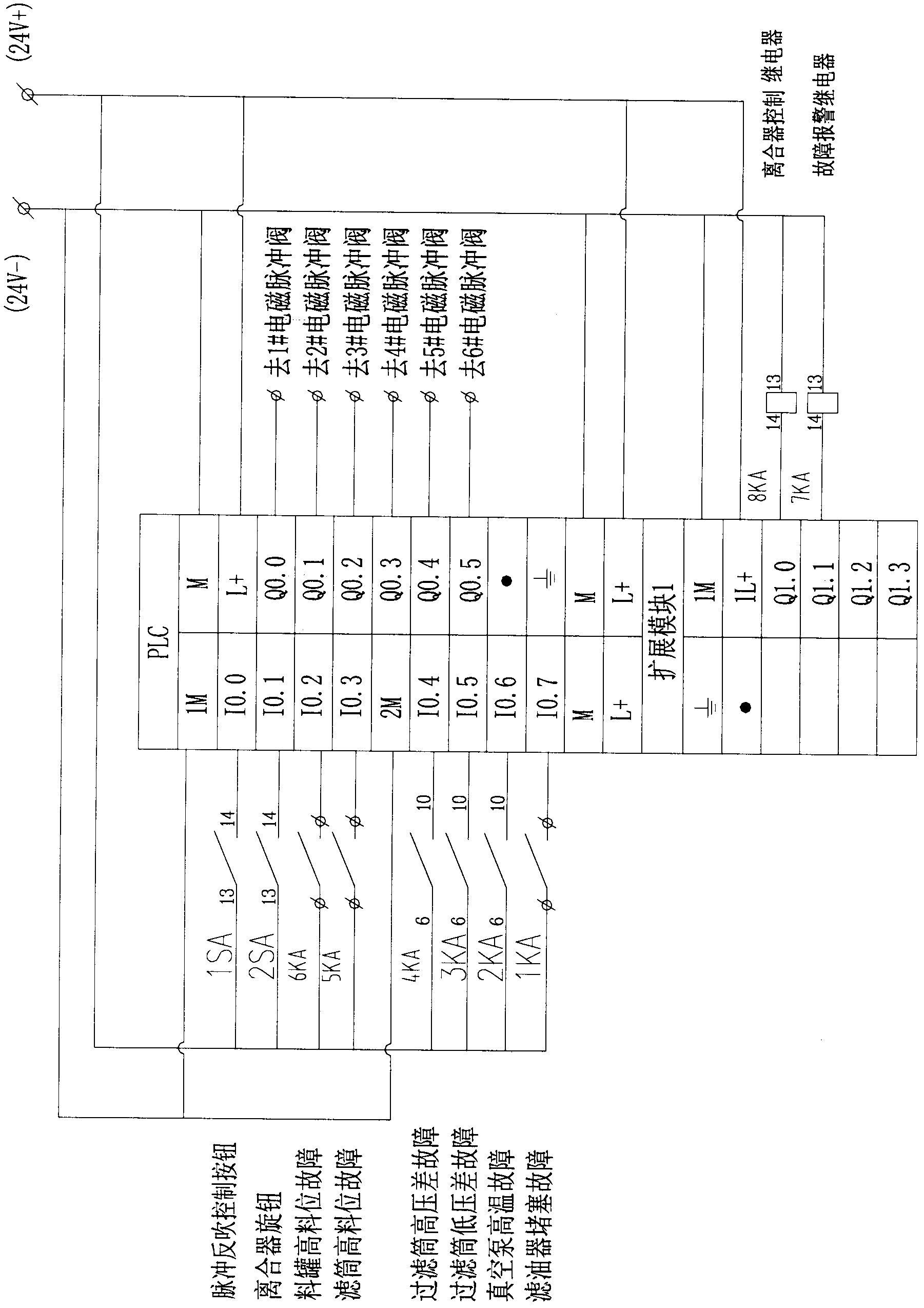
[0009] like figure 1 As shown, the control circuit of the mobile suction device of the present invention includes a programmable logic controller PLC, a pulse blowback control button, a clutch knob, a high material level detection circuit for a material tank, a high material level detection circuit for a filter cartridge, and a differential pressure detection circuit for a filter cartridge , Vacuum pump high temperature detection circuit, oil filter blockage fault detection circuit, electromagnetic pulse valve, clutch control relay, fault alarm relay. The pulse blowback control button, the clutch knob, the high material level detection circuit of the material tank, the high material level detection circuit of the filter cartridge, the differential pressure detection circuit of the filter cartridge, the high temperature detection circuit of the ...


PUM


Abstract

The invention discloses a mobile suction device which comprises a device body and a control circuit; the control circuit comprises a pulse jet cleaning control button, a clutch knob, a material tank high level detection circuit, a filter cylinder high level detection circuit, a filter cylinder differential pressure detection circuit, a vacuum pump high temperature detection circuit, an oil filter obstruction failure detection circuit, an electromagnetic pulse valve, a clutch control relay, and a fault alarm relay; the mobile suction device is characterized in that the control circuit also comprises a PLC; the pulse jet cleaning control button, the clutch knob, the material tank high level detection circuit, the filter cylinder high level detection circuit, the filter cylinder differential pressure detection circuit, the vacuum pump high temperature detection circuit, and the oil filter obstruction failure detection circuit are respectively connected with an input end of the PLC; the electromagnetic pulse valve, the clutch control relay, and the fault alarm relay are respectively connected with an output end of the PLC. Compared with the prior art, the invention has the following beneficial effect that PLC is adopted to substitute for tedious hardware control circuits in the prior art, which reduces the failure rate of hardware circuits, increases the calculating function and the logic operation function, and ensures the reliability of electrical equipment operation.

Description

technical field [0001] The invention relates to a mobile suction device, which belongs to the field of dust removal equipment. Background technique [0002] Mobile suction devices are widely used in thermal power generation, metallurgy and other industries to collect, transport or clean various granular and powdery materials. The control system of the existing mobile suction device mostly consists of relays and contactors to form a hardware control loop, which has the disadvantages of complex circuit structure, high failure rate, and inconvenient maintenance. Contents of the invention [0003] The invention provides a mobile suction device with simple circuit structure and low failure rate, and achieves the purpose of the invention by adding PLC (programmable logic controller) to the control circuit. [0004] The present invention is achieved through the following technical solutions: [0005] A mobile suction device, comprising a device body and a control circuit, the c...

Claims


Application Information

Patent Timeline
Patent Type & Authority Applications(China)
IPC IPC(8): B01D46/46B01D46/24
Inventor 傅惠新
Owner 傅惠新
Why Eureka
Try Eureka