Limitation overload large cutting-in impact resistant type dedicated blade

An impact-resistant and blade-resistant technology, applied in the direction of tools for lathes, accessories of tool holders, turning equipment, etc., can solve the problems of restricting the improvement of production efficiency, low tool life, and easy impact of tools, and achieves improved strength and The effect of cutting process accuracy, improving cutting efficiency and reducing cutting resistance

Inactive Publication Date: 2013-06-05
HARBIN UNIV OF SCI & TECH
View PDF7 Cites 1 Cited by
  • Summary
  • Abstract
  • Description
  • Claims
  • Application Information

AI Technical Summary

Problems solved by technology

[0003] The purpose of the present invention is to provide a special impact-resistant blade with extreme super-heavy load and large depth of cut to solve the problem that the current turning tool used in turning is a single-edge welded turning tool. The tool is easily broken by impact, and because the tool is not set The chip flute is easy to cause the cutting edge of the tool and the chip to produce a knife-chip bonding phenomenon, and the service life of the tool is low, which seriously restricts the improvement of production efficiency.

Method used


Image

  • Limitation overload large cutting-in impact resistant type dedicated blade
  • Limitation overload large cutting-in impact resistant type dedicated blade
  • Limitation overload large cutting-in impact resistant type dedicated blade

Examples


specific Embodiment approach 1

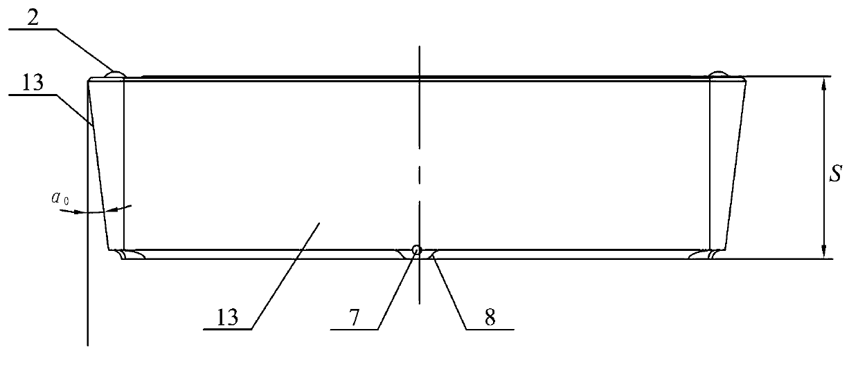
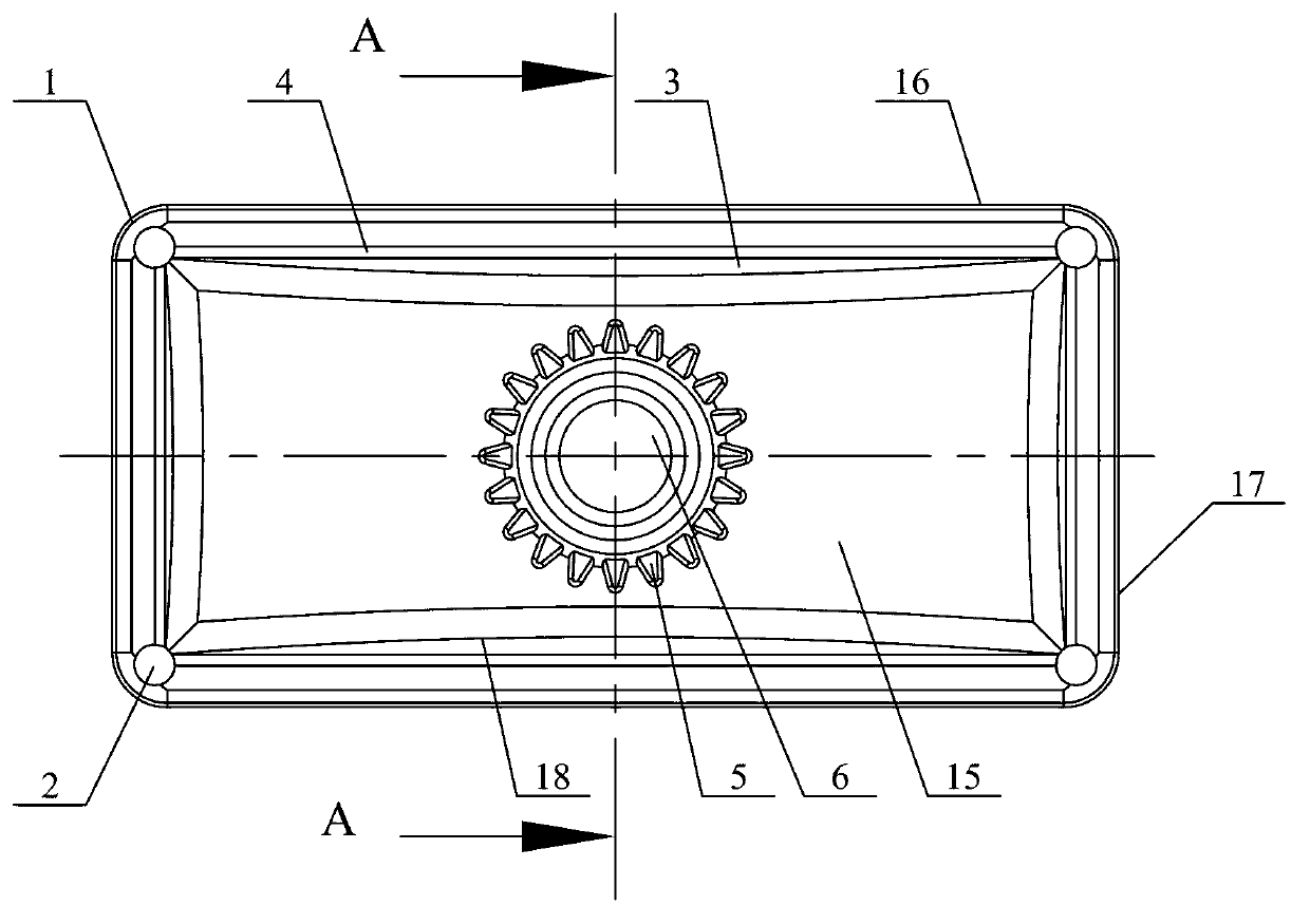
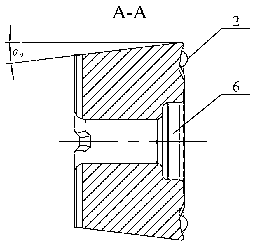
[0019] Specific implementation mode one: as Figure 1-Figure 6 As shown, the extreme super-heavy load and large depth of cut impact-resistant special blade of this embodiment has a horizontal cross-sectional shape of a rectangle, and the cross-sectional shape of the blade parallel to the length direction and the cross-section parallel to the width direction is isosceles Trapezoidal shape, the area of ​​the bottom surface of the blade is smaller than the area of ​​the rake face of the blade, a long cutting edge 16 is processed at the two long edges of the rake face of the blade, and a short cutting edge 17 is processed at the two short edges of the rake face of the blade respectively, The four corners of the rake face of the blade are respectively processed with double-arc knife tips 1, and the middle part of the rake face of the blade is provided with a rectangular protruding platform 15. The area of ​​the protruding platform 15 is smaller than the area of ​​the rake face of th...

specific Embodiment approach 2

[0020] Specific implementation mode two: combination Figure 1-Figure 3 and Figure 5 with Image 6 Note that four hemispherical protrusions 2 are provided on the rake face of the insert in this embodiment adjacent to the four double-arc-shaped tool tips 1, and the hemispherical protrusions 2 are arranged on the diagonal of the rake face of the insert. The undisclosed technical features in this embodiment are the same as those in the first embodiment.

specific Embodiment approach 3

[0021] Specific implementation mode three: combination figure 1 with Figure 5 Note that the thickness S of the blade described in this embodiment is 8-10 mm. meet strength requirements. The undisclosed technical features in this embodiment are the same as those in the second embodiment.


PUM


Abstract

The invention provides a limitation overload large cutting-in impact resistant type dedicated blade and belongs to the technical field of cutting tools used for lathe work. The limitation overload large cutting-in impact resistant type dedicated blade aims at solving the problems that a cutting tool is prone to breaking when impacted due to the fact that the existing cutting tool used in current lathe work is a single-blade welded type lathe tool, the cutting edge of the cutting tool and chips are prone to producing a tool-chip cementation phenomenon due to the fact that no chip breaker groove is formed in the cutting tool, service life of the cutting tool is short, and production efficiency is seriously restricted. A long cutting edge and a short cutting edge are processed in the edge position of the front tool face of the blade. A double-arc-shaped tool nose is processed in the corner portion of the front tool face of the blade. The side face of a protruding platform of the front tool face of the blade is a round-arc-shaped concave surface. An arc-shaped chip breaker groove is composed of an area which is enclosed by the round-arc-shaped concave surface and the front tool face of the blade. Guide grooves are formed around the bottom portion of the arc-shaped chip breaker groove. Tooth form grooves are processed on the periphery of a fastening screw counter bore. A tool bottom overflow and heat dissipation hole is formed in a protruding pillar in the bottom face of the blade. A tool bottom center heat dissipation groove is formed between two supporting bosses. The limitation overload large cutting-in impact resistant type dedicated blade is used for large cutting-in lathe work in heavy forging blank rough machining.

Description

technical field [0001] The invention belongs to the technical field of cutting tools for turning, and in particular relates to a special impact-resistant blade with extreme super-heavy load and large depth of cut. Background technique [0002] The large-scale hydrogenation cylinder blank is directly forged, and the weight can reach more than 400 tons. There are many forging defects on the surface to be processed that ordinary forgings do not have, such as: forging shovels, scale, forging cracks and metal coverings, etc.; The materials used in the hydrogen cylinder section are quite special and have strong high temperature toughness. At present, turning and milling are required for the processing of hydrogenation cylinders. For example, the cutting tool used in turning processing is a single-edged welded turning tool. The cutting amount caused by forging defects during the processing changes greatly, and the mechanical impact on the cutting tool is always dynamic. During the...

Claims


Application Information

Patent Timeline
Patent Type & Authority Applications(China)
IPC IPC(8): B23B27/22
Inventor 程耀楠刘利吴明阳何耿煌孙守慧胡强
Owner HARBIN UNIV OF SCI & TECH
Why Eureka
Try Eureka