A spot welding machine hot air circulation system

A circulation system and spot welding machine technology, applied in welding equipment, auxiliary welding equipment, welding/cutting auxiliary equipment, etc., can solve the problems of low product qualification rate, high energy consumption of equipment, unstable quality, etc., and achieve high thermal efficiency, Small fluctuations in soldering temperature and improved soldering reliability

Active Publication Date: 2015-11-11
KUSN WANSHENG ELECTRONICS
View PDF8 Cites 0 Cited by
  • Summary
  • Abstract
  • Description
  • Claims
  • Application Information

AI Technical Summary

Problems solved by technology

[0002] During the processing and production process of the existing spot welding machine, the air inlet of the blower is used to inhale the air of the external environment, and then the air outlet of the blower passes the inhaled air through the heating device to obtain the hot air required for welding to weld the product. The most important thing is the air in the external environment, and the temperature of the external environment fluctuates greatly. If the blower sucks in the cold air from the outside for a long time in a cold environment like winter, because the inhaled cold air, in order to maintain the normal welding work of the spot welder, heating The device is in a heating state for a long time, which is easy to cause equipment failure. At the same time, the product qualification rate is very low, the quality is unstable, and the energy consumption of the equipment is high.

Method used


Image

  • A spot welding machine hot air circulation system
  • A spot welding machine hot air circulation system

Examples


Embodiment 1

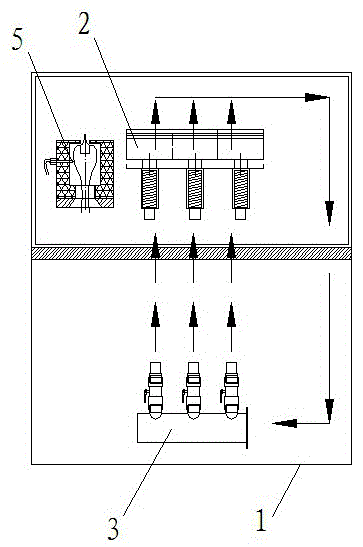
[0015] Such as figure 1 As shown, a spot welder hot air circulation system includes a welding box 1, a heating device 2 and a blower 3, the heating device 2 and the blower 3 are arranged in the welding box 1, the heating device 2 is arranged at the air outlet of the blower 3, and the blower 3 The air inlet is used to inhale the air in the welding box 1, and the door of the welding box 1 is provided with a sealing device for sealing the air in the welding box 1 box.

[0016] Since the sealing device of the welding box 1 strengthens the sealing of the box room, and at the same time, the air inlet of the blower 3 sucks the hot air in the box room, and then blows the hot air out from the air outlet, and passes through the heating device 2, so that the hot air in the box room can be circulated use. Hot air circulation is even and efficient. The air source is driven by the circulation blower 3 to drive the wind wheel through the heating device 2, and the hot air is sent out, and t...

Embodiment 2

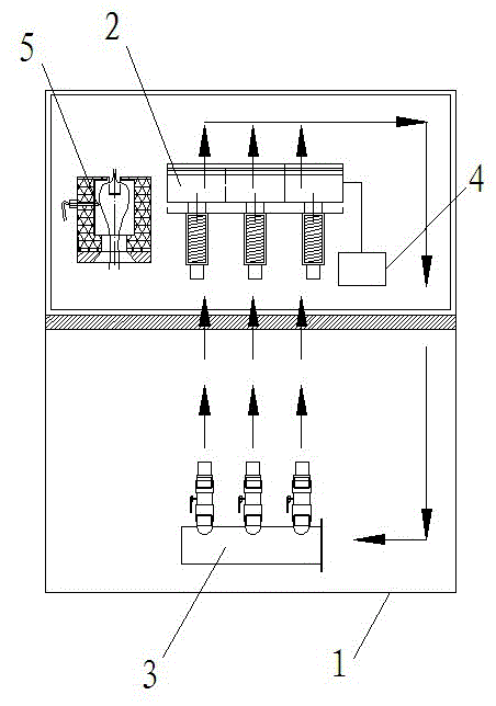
[0018] Such as figure 2 As shown, the rest is the same as that of Embodiment 1, except that it also includes a temperature control device 4 for detecting the temperature in the welding box and automatically controlling the operation of the heating device 2 . The temperature control device 4 is set. After working for a period of time, the thermal energy in the chamber will be more or less lost. At this time, the welding temperature in the chamber does not meet the work requirements. The temperature control device 4 automatically controls the heating device 2 to work to meet the needs of the work. Compensate for the heat energy in the chamber.

[0019] The beneficial effects of adopting this technical solution are: high thermal efficiency, energy saving and environmental protection, and at the same time, small fluctuations in welding temperature, effectively ensuring product quality stability, shortening welding cycle, and improving welding reliability.


PUM


Abstract

The invention discloses a spot welder hot air circulating system which comprises a welding box, a heating device and an air blower. The heating device and the air blower are arranged in the welding box, the heating device is arranged on an air outlet of the air blower, and an air inlet of the air blower is used for inhaling air inside the welding box. The spot welder hot air circulating system has the advantages of being high in heat efficiency, energy-saving and environment-friendly, and small in welding temperature fluctuation at the same time, effectively guaranteeing quality and stability of products, shortening welding cycle, and improving welding reliability.

Description

technical field [0001] The invention relates to a spot welding machine, in particular to a hot air circulation system of the spot welding machine. Background technique [0002] During the processing and production process of the existing spot welding machine, the air inlet of the blower is used to inhale the air of the external environment, and then the air outlet of the blower passes the inhaled air through the heating device to obtain the hot air required for welding to weld the product. The most important thing is the air in the external environment, and the temperature of the external environment fluctuates greatly. If the blower sucks in the cold air from the outside for a long time in a cold environment like winter, because it sucks in cold air, in order to maintain the normal welding work of the spot welder, heating The device is in a heating state for a long time, which is easy to cause equipment failure. At the same time, the product qualification rate is very low, ...

Claims


Application Information

Patent Timeline
Patent Type & Authority Patents(China)
IPC IPC(8): B23K37/00
Inventor 杨必祥胡鹏
Owner KUSN WANSHENG ELECTRONICS
Why Eureka
Try Eureka