Damping structure for decelerating dust collector wire winding wheel

A technology of damping structure and winding wheel, which is applied in the direction of vacuum cleaners, cleaning equipment, household appliances, etc., and can solve the problems of fast recovery of power cords, power cord plugs hurting people, and entangled cords, etc.

Inactive Publication Date: 2013-06-05
NANJING LG PANDA APPLIANCES
View PDF7 Cites 10 Cited by
  • Summary
  • Abstract
  • Description
  • Claims
  • Application Information

AI Technical Summary

Problems solved by technology

[0013] The purpose of this invention is to solve the problems in the prior art that the recovery speed of the power cord wound on the reel is too fast, which leads to the confusion of the winding and the injury of the power cord plug, etc., and provides a damping structure for the deceleration of the reel of the vacuum cleaner.

Method used


Image

  • Damping structure for decelerating dust collector wire winding wheel
  • Damping structure for decelerating dust collector wire winding wheel
  • Damping structure for decelerating dust collector wire winding wheel

Examples


Embodiment Construction

[0059] The present invention will be described in detail below in conjunction with the accompanying drawings and embodiments.

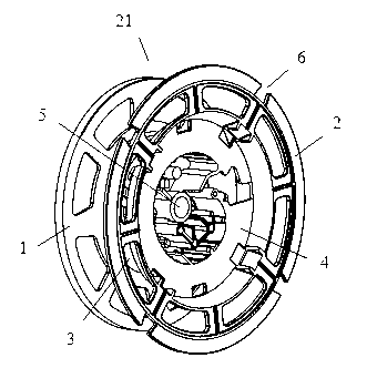
[0060]A damping structure for the deceleration of the reel of the vacuum cleaner, including the reel 21 formed by the left reel 1, the right reel 2 and the hollow bobbin 3 winding the power cord between them, the shaft tube 5 in the center of the bobbin 3, and the right The annular groove 4 on the outer surface of the wheel disc 2 is provided with an oil damping structure 8 combined with the connecting shaft 7 .

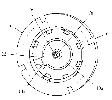
[0061] figure 2 It is a schematic diagram of the installation structure of the winding wheel and oil damping in the present invention, image 3 is a schematic diagram of the three-dimensional structure of the upper cover in the oil damping structure, Figure 4 is the schematic diagram of the three-dimensional structure of the friction disc in the oil damping structure, Figure 5 is a schematic diagram of the three-dimensional structure o...


PUM


Abstract

The invention discloses a damping structure for decelerating a dust collector wire winding wheel, and belongs to winding devices of dust collector wires. The damping structure for decelerating the dust collector wire winding wheel comprises a left wheel plate, a right wheel plate, a wire winding wheel and a shaft pipe, wherein the wire winding wheel is formed by a hollow wire winding shaft wound by power lines, and the shaft pipe is placed in the middle of the wire winding shaft. An oil damping structure combined with a connection shaft, or a magnet oil damping structure or an oil damping structure transmitted by gears is placed in an annular groove in the outer side face of the right wheel plate. Due to the fact that the wire winding wheel is stressed by resistance produced by the oil damping structure, or an additionally placed permanent magnet or additionally arranged gears with different transmission ratios in the process of back rotation of the wire winding wheel, rotational speed of the wire winding wheel is reduced. Therefore, bad phenomena caused by fast back rotation of the wire winding wheel are avoided.

Description

technical field [0001] The invention relates to a wire winding device for a vacuum cleaner, in particular to a damping structure for decelerating a wire reel of a vacuum cleaner. Background technique [0002] Vacuum cleaner is a cleaning and sanitary electrical device used to remove dust from floors, carpets, walls, furniture, clothing and various gaps. [0003] According to the classification of vacuum cleaners, they can be divided into vertical vacuum cleaners, horizontal (tank) vacuum cleaners and portable vacuum cleaners. [0004] The general structure of a horizontal vacuum cleaner mainly includes a vacuum cleaner motor that generates suction by introducing current, a suction nozzle that forms an air path system, a suction tube, a suction hose, a filter device, and a dust collection device that collects inhaled objects. [0005] The top of the body of the horizontal vacuum cleaner is equipped with a suction pipe interface for connecting the vacuum hose, and the rear of...

Claims


Application Information

Patent Timeline
Patent Type & Authority Applications(China)
IPC IPC(8): B65H75/48A47L9/00
Inventor 徐昕皓洪明
Owner NANJING LG PANDA APPLIANCES
Why Eureka
Try Eureka