Quench machining tool

A quenching machine tool and quenching device technology, applied in the field of quenching machine tools, can solve the problems of inconvenient loading and unloading, lifting and moving, unsafe lifting process, large moving resistance, etc., and achieve simple structure, good lifting balance and small moving resistance Effect

Inactive Publication Date: 2013-06-05
YANCHENG KWONG HING ELECTRIC
View PDF0 Cites 1 Cited by
  • Summary
  • Abstract
  • Description
  • Claims
  • Application Information

AI Technical Summary

Problems solved by technology

The existing quenching machine tools are not very convenient in loading and unloading, lifting and moving, the movement resistance is relatively large, and there is no focus point when lifting, and the lifting process is unsafe

Method used


Image

  • Quench machining tool

Examples


Embodiment Construction

[0008] The specific content of the present invention will be described in detail below in conjunction with the accompanying drawings and specific embodiments.

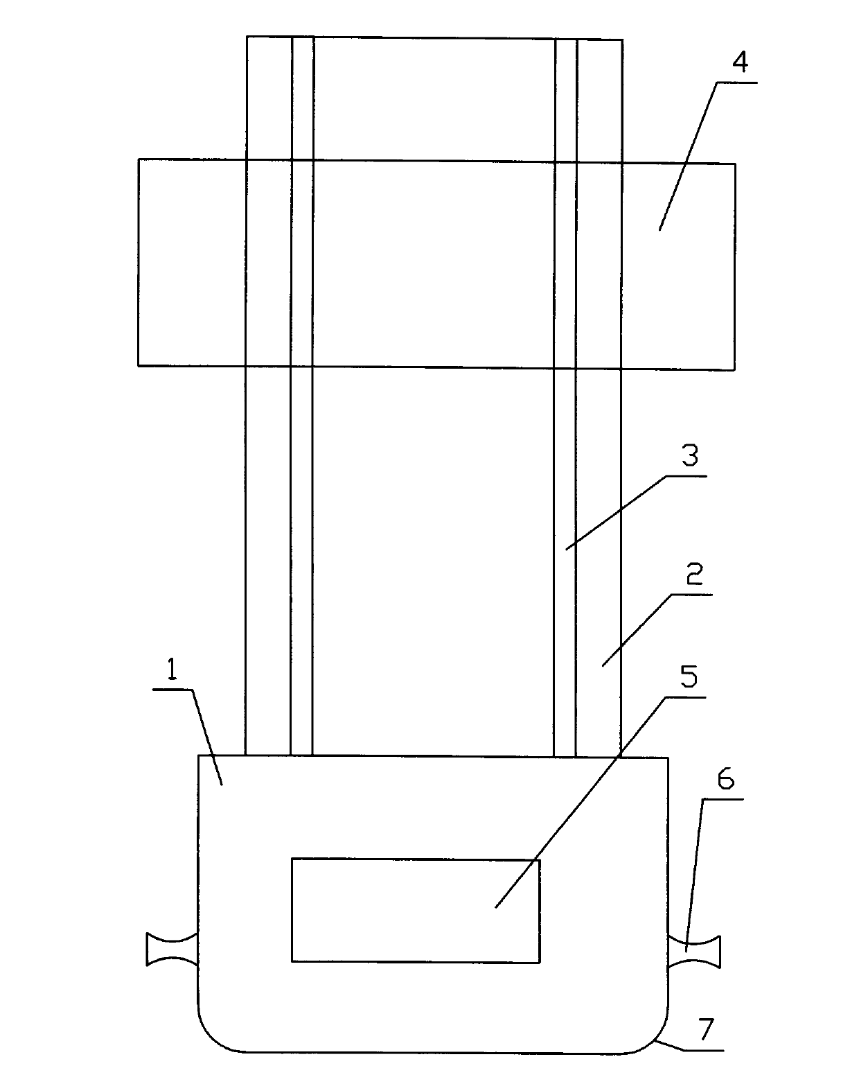
[0009] Such as figure 1 As shown, the quenching machine tool includes: a base 1 and a bed 2 arranged on the base 1, a slide rail 3 is arranged on the bed 2, and a quenching device 4 is slidably arranged on the slide rail 3, and on the base 1 is provided with a drive device 5 , and arc-shaped lifting columns 6 are arranged symmetrically on both sides of the base 1 , and arc-shaped surfaces 7 are arranged around the base 1 .

[0010] When in use, the driving device 5 drives the quenching device 4 to slide on the slide rail 3, and the quenching device 4 performs quenching operations on large shafts, gears and disc-shaped parts. When the above-mentioned quenching machine tool is hoisted, it can be suspended by the arc-shaped lifting column 6. The lifting stability is good and the lifting is safe. Small.


PUM


Abstract

The invention discloses a quench machining tool which can be moved conveniently. The quench machining tool comprises a base and a lathe bed arranged on the base, wherein the lathe bed is provided with a sliding rail; a quench device is glidingly arranged on the sliding rail; a driving device is arranged in the base; arc-shaped hoisting pillars are symmetrically arranged on both sides of the base; and arc-shaped surfaces are arranged on the periphery of the base. The quench machining tool has the advantages of being simple in structure, low in moving resistance, convenient to assemble, disassemble, hoist and move, high in hoisting balance and safe in hoisting.

Description

technical field [0001] The invention relates to a quenching machine tool. Background technique [0002] Quenching machine tools are used for the quenching of large shafts, gears and disk parts. The structure of the existing quenching machine tool mainly includes: a base and a bed arranged on the base, a slide rail is arranged on the bed, a quenching device is slidably arranged on the slide rail, and a driving device is arranged in the base. When in use, the driving device drives the quenching device to slide on the slide rail, and the quenching device performs quenching operation on large shafts, gears and disc-shaped parts. The existing quenching machine tool is not very convenient in loading and unloading, lifting and moving, and the moving resistance is relatively large, and there is no focus point when lifting, and the lifting process is unsafe. Contents of the invention [0003] The technical problem to be solved by the present invention is to provide a conveniently...

Claims


Application Information

Patent Timeline
Patent Type & Authority Applications(China)
IPC IPC(8): C21D1/62
Inventor 王军
Owner YANCHENG KWONG HING ELECTRIC
Why Eureka
Try Eureka