Integrated spontaneous heating floor board and bi-directional electric connecting plug

A self-heating, integrated technology, applied in connection, space heating and ventilation, circuits, etc., can solve problems such as potential safety hazards, pre-embedded heating wires, difficult production and processing, etc.

Inactive Publication Date: 2014-12-24
江苏德威木业有限公司
View PDF7 Cites 2 Cited by
  • Summary
  • Abstract
  • Description
  • Claims
  • Application Information

AI Technical Summary

Problems solved by technology

Although this document does not describe how to wire the heating wires, it can be inferred from the above-mentioned content of "grinding the heating wires to prevent the through-holes of adjacent floor boards from being dislocated" that the heating wires pass through the floor boards piece by piece. Not only is the installation troublesome, but also the heating wire will be damaged during installation, which poses a great safety hazard. In addition, once the heating wire somewhere is damaged and does not conduct, all floor boards will not be able to heat up
[0007] Chinese patent document CN2495931Y (Patent No. ZL01249911.0) discloses a "heat-generating floor", which records "the structure of the utility model is as follows: figure 1 and figure 2 As shown, it is composed of a reinforced floor board 1 with insulation performance and an electric heating wire 2 embedded in the reinforced floor board 1. A thermal protector 3 and a fuse 6 are connected in series in the electric heating wire 2. In the reinforced floor board 1 There is a longitudinal protrusion 4 on the left end face of the floor board, and a longitudinal groove 5 is arranged on the right end face. The longitudinal protrusion 4 can be matched with the longitudinal groove 5. A plug 7 is respectively installed on the left and right sides of the upper end face of the reinforced floor board 1, and a plug 7 is arranged on the lower end face. A socket 8 is respectively installed at the position corresponding to the upper end surface 7, the plug 7 is matched with the socket 8 and the left and right groups of plugs 7 and sockets 8 on the upper and lower end surfaces are respectively connected with the two ends of the electric heating wire 2 in the reinforced floor board 1 Constitute an electrification circuit", the heating floor uses the electric heating wire 2 to generate heat for heating and heating, and there are the following problems: 1. Since the electric heating wire 2 usually has a circular cross section, the heat is along the radius of the cross section when heating. The direction diverges to the surroundings, causing part of the heat to be dissipated to the bottom of the floor, which greatly wastes energy
2. Since the electric heating wire 2 is usually slender, the effective heat dissipation area above the floor is small. If you want to obtain a better heat dissipation effect, you must lay the electric heating wire 2 relatively densely. increased manufacturing costs
3. The electric heating wire 2 is usually relatively soft, so it is more troublesome to pre-embed the electric heating wire 2 spirally embedded in the laminate flooring block 1, and the production and processing are more difficult
4. The heating efficiency of the heating wire is low, about 88% to 92%, and the heat is uneven, and high temperature will be generated locally, which is easy to age
Among the above three installation methods, the first method of slotting usually adopts a row of knives to slot vertically and horizontally, which will form sharp edges at the turning, which is easy to damage the insulation skin of the wire; the second installation method is more difficult to process and is not convenient Large-scale industrial production; the "composite floor" in the third way includes a wide range. For example, laminate flooring is a kind of balanced paper layer, density board, decorative paper layer and wear-resistant paper layer from bottom to top. The composite floor formed by hot pressing, so structurally speaking, this kind of composite floor cannot pre-embed the heating wire, so the third installation method of the heating wire in this document cannot be implemented by those skilled in the art
The above three installation methods all have the problem of making complex troubles
[0011] Again, it is proposed in this document that the first connector, the second connector, the plug, the first joint and the second joint are all features of a waterproof structure, but it does not solve the waterproof problem of the entire floor system
Although the first joint and the second joint adopt a waterproof structure, there is no mention of how to solve the problem of waterproofing the connection between the two joints and the heating wire, nor does it involve the contact between the two joints and the floor plate. The problem of sealing and waterproofing, when the floor system is not energized for a period of time, the water vapor in the air will enter the interior of the floor from the gap between the joint and the floor body, and condense at the joint between the joint and the heating wire. When the power is turned on, there will be serious leakage, which will cause the touch protector to trip immediately. If the touch protector is not installed, it will cause overheating or even burn the floor due to the generation of large current

Method used


Image

  • Integrated spontaneous heating floor board and bi-directional electric connecting plug
  • Integrated spontaneous heating floor board and bi-directional electric connecting plug
  • Integrated spontaneous heating floor board and bi-directional electric connecting plug

Examples


Embodiment 1

[0126] (Example 1, integrated self-heating floor)

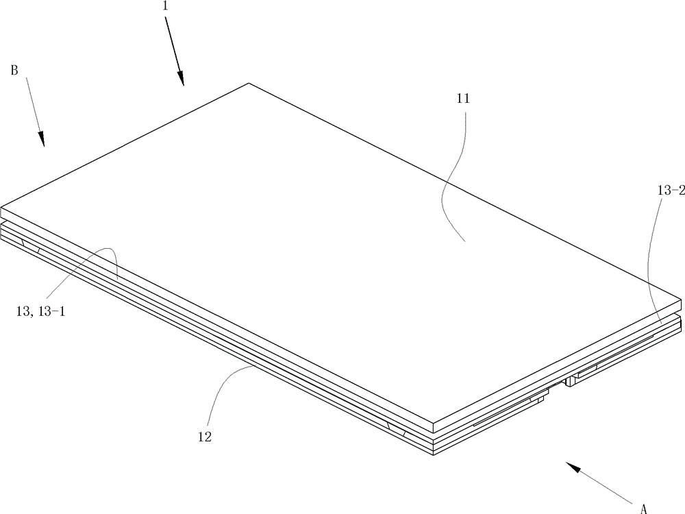
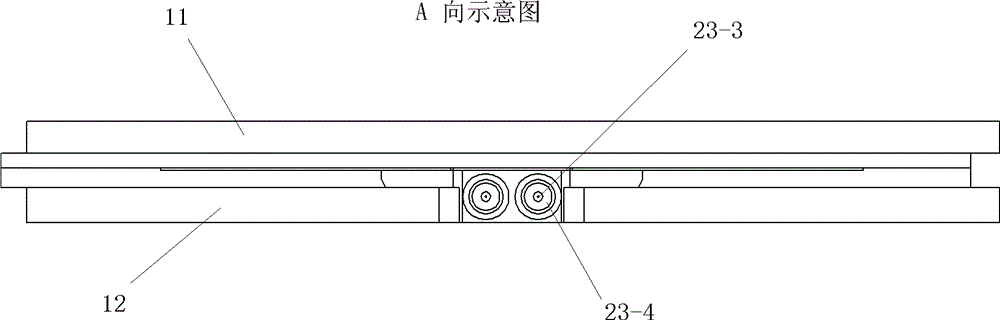
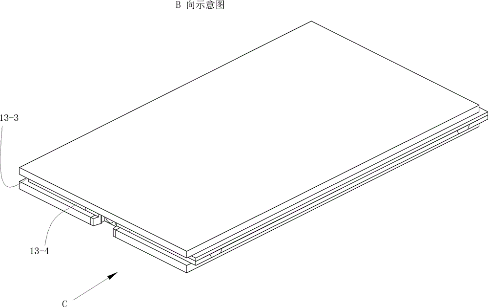
[0127] See figure 1 with Figure 8 , The integrated self-heating floor 1 of the present invention includes a panel 11 , a lower body 12 and a self-heating component 2 . The panel 11 is bonded and fixed on the lower body 12 from above to form a floor body with an internal cavity. An inserting part 13 is provided around the floor body of the integrated self-heating floor 1 . The insertion part 13 on the front side of the floor body of the integrated self-heating floor 1 is the front side insertion tenon 13-1, and the insertion part 13 on the right side of the floor body of the integrated self-heating floor 1 is the right side insertion part 13-1. Joint 13-2, the insertion part 13 located on the rear side of the floor body of the integrated self-heating floor 1 is the rear insertion groove 13-3, the insertion part located on the left side of the floor body of the integrated self-heating floor 1 Part 13 is the left insertion ...

Embodiment 2

[0162] (Example 2, integrated self-heating floor)

[0163] The rest of this embodiment is the same as that of Embodiment 1, except that the length of the integrated self-heating floor of this embodiment along the long side of the floor is the length of the integrated self-heating floor 1 of Embodiment 1 along the long side. half the length.

Embodiment 3

[0164] (Example 3, integrated self-heating floor)

[0165] The rest of this embodiment is the same as that of Embodiment 1, the difference is that: the upper surface of the middle part of the lower body 12 of the integrated self-heating floor 1 is only provided with one upper groove, and the lower body 12 is in the middle of the upper groove. Two wire slots parallel to each other with upward openings are arranged at the front-to-back middle part of the slot wall facing upward along the left-right direction. The socket base 23-1 has one heater slot formed during injection molding, which corresponds to the upper groove of the lower body.

[0166] See Figure 23 , the electric heater 21 also has only one piece corresponding to the upper groove of the lower body 12 of the integrated self-heating floor 1 . The electrical connection device 24 includes two copper wires 24-1. The two copper wires 24-1 are called first copper wire 24-1a and second copper wire 24-1b in sequence. The...


PUM


Abstract

The invention discloses an integrated spontaneous heating floor board which comprises a floor board main body and a spontaneous heating assembly. The floor board main body comprises a face plate and a bottom main body. The spontaneous heating assembly is arranged between the face plate and the bottom main body. The face plate is fixedly connected with the bottom main body from top to bottom. The integrated spontaneous heating floor board is characterized in that the floor board main body is provided with an internal cavity. Plug-in portions are arranged on the periphery of the floor board main body. The spontaneous heating assembly is a waterproof electric heating assembly which comprises electric heating pieces, a transmission unit and two mounting seats, wherein the two mounting seats are respectively arranged at the left end and the right end of the electric heating pieces. The electric heating pieces are electrically connected with the transmission unit through electrodes of the electric heating pieces and corresponding electric connection components. The electric heating pieces of the spontaneous heating assembly are arranged in the internal cavity of the floor board main body. The mounting seats of the spontaneous heating assembly are fixedly connected and embedded in the floor board main body, and the two mounting seats are respectively exposed out of the left side and the right side of the floor board main body. Therefore, the left mounting seat and the right mounting seat of the spontaneous heating assembly are used as corresponding power supply plug connecting pieces on the left side and the right side of the integrated spontaneous heating floor board.

Description

technical field [0001] The invention relates to a product in the field of building decoration, in particular to a self-heating floor and a bidirectional electrical connection plug for electrically connecting adjacent self-heating floors. Background technique [0002] At present, the form of self-heating floor is electric heating floor, which has become a new heating method. It is to lay electric heating material in the floor, and heat the floor by heating the electric heating material in the floor to heat the floor. [0003] When the traditional floor is installed, it is assembled in the form of tenon and tenon groove on the surrounding sides. There are two common forms of tenon and tenon groove. One is to insert the flat tenon and the flat groove into each other. Assembling, the other is to set corresponding concave-convex parts on the tenon head and tenon groove to carry out mutual locking for assembly. The floor of the former assembly method is usually called a flat-inse...

Claims


Application Information

Patent Timeline
Patent Type & Authority Patents(China)
IPC IPC(8): E04F15/02E04F15/04F24D13/02H01R31/06H01R13/02H01R13/46
Inventor 葛林葛鑫琰
Owner 江苏德威木业有限公司
Why Eureka
Try Eureka