Flame-retardant optical fiber composite cable

A fiber optic composite cable and optical cable technology, which is applied in the direction of insulated cables, cables, circuits, etc., can solve the problems of frequent replacement, small elongation at break, aging of optical cable insulation and sheath, and improve safety and stability. Improve the compressive and tensile performance, good effect of anti-corrosion performance

Inactive Publication Date: 2018-11-30
SHANDONG QUANXING YINQIAO OPTICAL & ELECTRIC CABLE SCI & TECH DEV
View PDF0 Cites 1 Cited by
  • Summary
  • Abstract
  • Description
  • Claims
  • Application Information

AI Technical Summary

Problems solved by technology

[0002] Wire and cable are the carriers of power transmission or information transmission. They are widely used in industrial and civil electrical facilities. The use environment or occasions are different, and the requirements are different. Especially the use environment of wind power, metallurgy and chemical industries is harsh. Some specific performance requirements, the currently used PVC sheath material has poor flexibility, small elongation at break, poor crack resistance, no torsion, oil resistance, acid resistance, and corrosion resistance. The service life of the cable is short. Frequent replacement affects the normal operation of industrial production; in order to meet these special requirements, some manufacturers have to use silicone rubber or polyurethane materials, but the impact resistance of silicone rubber is relatively poor, the cable sheath is easy to crack, and the service life is short. The cost of polyurethane material is too high; and the existing cables have poor heat resistance and limited scope of application
[0003] With the modernization process of urban transformation in the future, the full load and overload of the line has become the norm, and the insulation and sheath of optical cables in a large number of buildings have been aging, which is easy to cause short circuit of the line and cause fire and casualties

Method used


Image

  • Flame-retardant optical fiber composite cable
  • Flame-retardant optical fiber composite cable
  • Flame-retardant optical fiber composite cable

Examples


Embodiment Construction

[0020] The following will clearly and completely describe the technical solutions in the embodiments of the present invention with reference to the accompanying drawings in the embodiments of the present invention. Obviously, the described embodiments are only some, not all, embodiments of the present invention. Based on the embodiments of the present invention, all other embodiments obtained by persons of ordinary skill in the art without making creative efforts belong to the protection scope of the present invention.

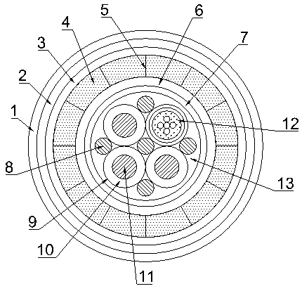
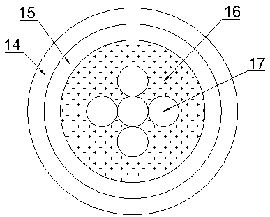
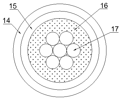
[0021] see Figure 1~3 , in an embodiment of the present invention, a flame-retardant optical fiber composite cable includes a cable core, and the cable core is formed by twisting a plurality of cable cores 9, an optical cable core 12 and a plurality of filling ropes 8, and a plurality of The cable core 9 and an optical cable core 12 are arranged in a ring shape inside the cable core. Each cable core 9 includes a cable conductor 11 and an insulating layer 10 c...


PUM

PropertyMeasurementUnit
thicknessaaaaaaaaaa

Abstract

The invention discloses a flame-retardant optical fiber composite cable comprising a cable core. The cable core is formed by a plurality of cable wire cores, an optical cable wire core and a pluralityof filling ropes in a twisted mode. The multiple cable wire cores and the optical cable wire core are annularly arranged inside the cable core. The filling ropes are arranged at the center defined bythe cable wire cores and the optical cable wire core and the outer sides of the externally tangent positions of the adjacent cable wire cores or the optical cable wire core. The exterior of the cablecore is coated with a polyethylene inside liner, the polyethylene inside liner is sequentially coated with an outer shielding layer, a silica gel fireproof layer, a mica tape layer, a high-flame-retardance halogen-free low-smoke flame-retardant sheath layer and a water-blocking layer, and the gaps between the polyethylene inside liner and the cable wire cores, the gap between the polyethylene inside liner and the optical cable wire core, and the gaps between the polyethylene inside liner and the filling ropes are filled with insulation foaming layers. According to the flame-retardant opticalfiber composite cable, the advantages of all materials are fully utilized, so that the overall oil resistance, acid resistance and anticorrosion properties of the cable are good, the cost is saved, the compressive property and the tensile property of the cable are further improved, the overall flexible property of the cable is good, and the service life of the cable is greatly prolonged.

Description

technical field [0001] The invention relates to the technical field of cables, in particular to a flame-retardant optical fiber composite cable. Background technique [0002] Wire and cable are the carriers of power transmission or information transmission. They are widely used in industrial and civil electrical facilities. The use environment or occasions are different, and the requirements are different. Especially the use environment of wind power, metallurgy and chemical industries is harsh. Some specific performance requirements, the currently used PVC sheath material has poor flexibility, small elongation at break, poor crack resistance, no torsion, oil resistance, acid resistance, and corrosion resistance. The service life of the cable is short. Frequent replacement affects the normal operation of industrial production; in order to meet these special requirements, some manufacturers have to use silicone rubber or polyurethane materials, but the impact resistance of si...

Claims


Application Information

Patent Timeline
Patent Type & Authority Applications(China)
IPC IPC(8): H01B7/02H01B7/17H01B7/18H01B7/28H01B7/282H01B7/285H01B7/29H01B7/295
CPCH01B7/02H01B7/17H01B7/18H01B7/1895H01B7/28H01B7/2806H01B7/2825H01B7/285H01B7/29H01B7/295
Inventor 韩玉权徐增
Owner SHANDONG QUANXING YINQIAO OPTICAL & ELECTRIC CABLE SCI & TECH DEV
Why Eureka
Try Eureka