Method for controlling gap between blade tip of turbine casing and blade tip of turbine rotor blade

A technology of turbine casing and turbine rotor, used in mechanical equipment, engine components, machines/engines, etc., to solve problems such as heavy weight and thrust loss

Active Publication Date: 2013-06-05
AECC COMML AIRCRAFT ENGINE CO LTD
View PDF6 Cites 15 Cited by
  • Summary
  • Abstract
  • Description
  • Claims
  • Application Information

AI Technical Summary

Problems solved by technology

[0004] In order to solve the problems of thrust loss and heavy weight caused by the engine active clearance control system using gas cooling or heating casing in the prior art, the present invention proposes a clearance control method that uses fuel oil to cool the turbine casing

Method used


Image

  • Method for controlling gap between blade tip of turbine casing and blade tip of turbine rotor blade

Examples


Embodiment Construction

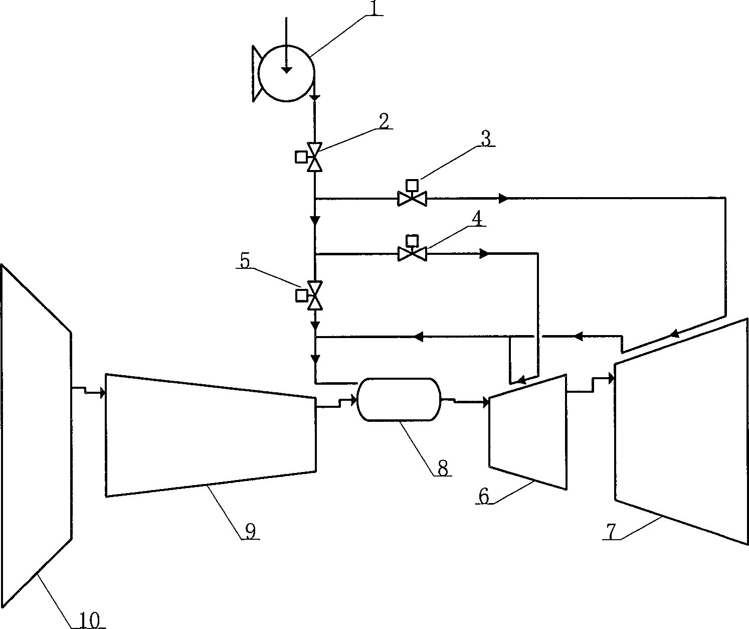
[0028] Such as figure 1 As shown, it schematically shows a clearance control system of a gas turbine engine according to an embodiment of the present invention. The gas turbine engine has a fan 10, a low-pressure compressor (not shown), a high-pressure compressor 9, a combustion chamber 8, a high-pressure turbine 6 and a low-pressure turbine 7, etc. in the airflow direction, wherein the low-pressure compressor and the low-pressure turbine 7 are connected to On one shaft, the high pressure compressor 9 and the high pressure turbine 6 are connected to the other shaft. In addition, in the circumferential and axial directions, all the above-mentioned engine components are surrounded by segmented casings, for example, the high-pressure turbine rotor 6 and the low-pressure turbine rotor 7 are respectively surrounded by high-pressure turbine casings and low-pressure turbine casings. Wherein, the high-pressure turbine casing and the low-pressure turbine casing are casings with annula...


PUM


Abstract

A method for controlling a gap between a blade tip of a turbine casing and a blade tip of a turbine rotor blade includes a first step of detecting temperature of the turbine casing, a second step of detecting rotating speed of the turbine rotor, a third step of transmitting fuel oil to the turbine casing and cooling, and a fourth step of calculating the actual gap between the turbine casing and the corresponding turbine rotor blade according to the temperature of the turbine casing and the rotating speed of the turbine rotor, and limiting the actual gap within the range of the target gap by controlling flow of the fuel oil in an oil transportation pipeline in the third step when the calculated actual gap is not within the range of a preset target gap. Due to the fact that the fuel oil is adopted to cool the casing, pressure loss of the fuel oil in the flowing process is low, the fuel oil is burned in a combustion chamber after heat exchange, and thereby thrust loss can not happen.

Description

technical field [0001] The invention relates to a method for controlling the clearance between a turbine casing and the tip of a turbine rotor blade. Background technique [0002] The main method of controlling the gap between the turbine casing and the tip of the turbine rotor blade is to control the thermal deformation of the turbine casing to control the gap between the turbine blade and the turbine casing within a more suitable range. Rough research shows that the use of an effective turbine active clearance control system can reduce fuel consumption by about 1%-2%, which is of great significance for improving the economy of civil aeroengines. The common turbine active clearance control is to use the gas from the fan or compressor outlet to impinge on the turbine casing, and use a logic control system to ensure that the engine maintains the best blade tip clearance during operation. The more common control strategy is: when cruising, the turbine casing is cooled by the ...

Claims


Application Information

Patent Timeline
Patent Type & Authority Applications(China)
IPC IPC(8): F01D11/16F01D25/14
Inventor 顾伟陈潇朱亚涛邓双国林蕾苏伟王志强
Owner AECC COMML AIRCRAFT ENGINE CO LTD
Why Eureka
Try Eureka