Oil pumping technique based on middle venting gas-prevention oil well pump

An oil-pumping and oil-pumping technology, which is applied to the components, pumps, and pump components of the pumping device for elastic fluids, can solve the problem of shortening the pump inspection period, reducing the fullness of the pump cavity, and the opening lag of the oil pump valve ball. and other problems to achieve the effect of reducing well workover costs, reducing environmental pollution and improving oil intake conditions

Inactive Publication Date: 2013-06-05
潘美林
View PDF0 Cites 4 Cited by
  • Summary
  • Abstract
  • Description
  • Claims
  • Application Information

AI Technical Summary

Problems solved by technology

There are two technically controversial issues about oil well pumps: one is whether the whole cylinder type oil well pump is better or the bushing type oil well pump is better; the other is whether it is better to have sand control grooves on the plunger or no sand control grooves
These gases occupy part of the volume of the pump chamber, which will reduce the fullness of the pump chamber, resulting in the lagging of the valve ball of the oil well pump, and even the phenomenon of "air lock"
"Hydraulic shock" also occurs during "air lock", causing vibration of the rod pumping system and accelerating its damage
As a result, pumping wells are frequently operated, shortening the pump inspection cycle, and increasing development costs

Method used


Image

  • Oil pumping technique based on middle venting gas-prevention oil well pump

Examples


Embodiment

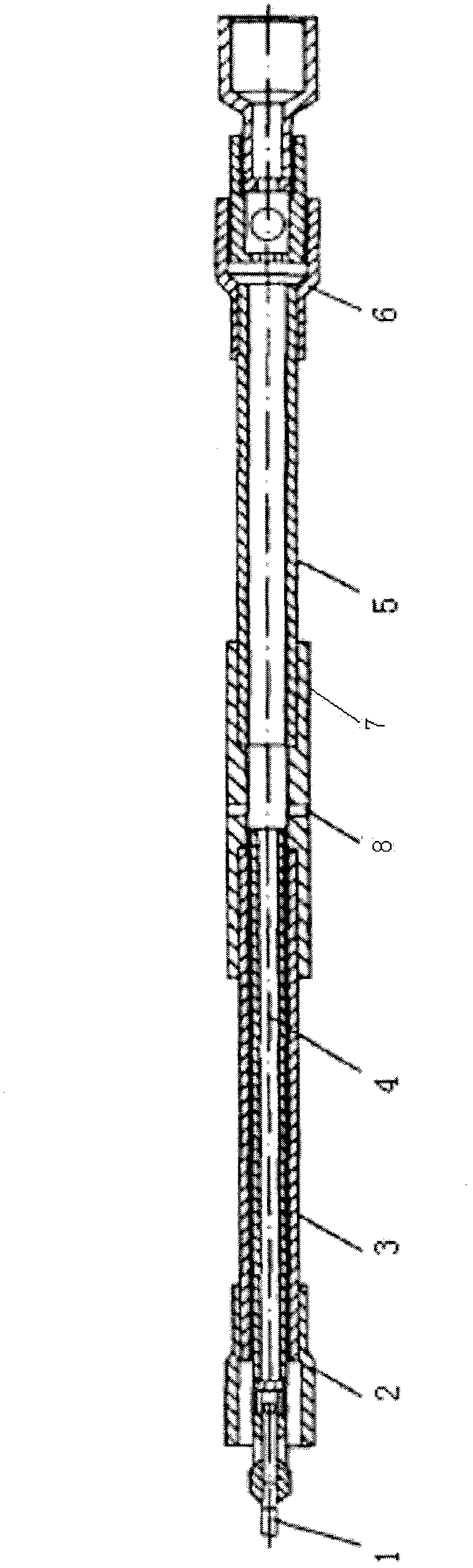
[0028] The oil pumping process based on the middle exhaust gas anti-air pump involved in the present invention comprises the following steps:

[0029] (a) First, turn on the power device, which drives the plunger connecting rod 1, and then drives the plunger 4 to move upward;

[0030] (b) The pressure in the 5 chambers of the lower pump barrel is reduced, the fixed valve is opened, and the upstream and downstream moving valves are closed;

[0031] (c) When the lower end of the plunger 4 goes up and exceeds the vent hole 8 in the middle of the upper pump barrel 3, the oil in the casing enters the pump barrel from the vent hole 8 under the action of submerged pressure. The space that is not filled in the pump barrel is replenished; on the other hand, the gas in the pump space under the exhaust groove of the pump barrel is discharged, so as to realize the exhaust function of the pump;

[0032] (d) The power unit drives the plunger connecting rod 1, and then drives the plunger 4 ...


PUM


Abstract

The invention discloses an oil pumping technique based on a middle venting gas-prevention oil well pump. The technique includes: (a) a power device is started to drive a plunger to move upward; (b) a fixed valve is opened and an upper traveling valve and a lower traveling valve are closed; (c) oil in a sleeve enters a pump cylinder from a venting hole under the action of the sinking pressure; and (d) the power device drives the plunger to move downward, the venting hole of the pump cylinder is sealed by the surface of the plunger, the traveling valves are opened, and oil in the lower portion of the pump cylinder is discharged to an oil pipe through an inner hole of the plunger. The technique improves the oil inlet conditions, and promotes fullness of a cavity of the pump cylinder below a venting groove of the pump cylinder. Therefore, compared with a conventional pump, the pump can effectively promote the pump efficiency. The oil pipe and the sleeve are communicated mutually through the venting groove in the middle of the pump cylinder. A second-time venting groove is formed in the pump cylinder, the effect that an oil drain device is not installed in the well can be achieved, and oil well maintenance cost and environmental pollution are reduced. Due to the fact that the venting grooves are formed in the pump cylinder, a pressure test can not be carried out on the whole pipe column after well completion.

Description

technical field [0001] The invention relates to an oil pumping process based on a mid-exhaust air-proof oil pump. Background technique [0002] Before the 20th century, the development of oil well pump technology at home and abroad was slow, and it was not until the middle of the 20th century that the whole barrel oil well pump was studied and produced simultaneously with the bushing type oil well pump. There are two technically controversial issues about oil well pumps: one is whether the whole barrel type oil well pump is better or the bushing type oil well pump is better; the other is whether it is better to have sand control grooves on the plunger or not to have sand control grooves. Until the 1980s, due to the significant improvement of the pump efficiency of the whole barrel pump, it is generally about 10% higher than that of the bushing pump, which prolongs the service life of the plunger pump barrel pair, and can save about 40% of high-quality steel. Instead of the ...

Claims


Application Information

Patent Timeline
Patent Type & Authority Applications(China)
IPC IPC(8): F04B47/00F04B53/06
Inventor 潘美林
Owner 潘美林
Why Eureka
Try Eureka