Pumps for temperature circulation circuits in automobiles

A temperature cycle and loop technology, which is applied to the components, pumps, and pump devices of pumping devices for elastic fluids, can solve the problems of surface pressure wear, loss, high surface compressive stress, etc., and achieve a compact structure, low cost effect

Active Publication Date: 2017-12-22
海拉有限双合股份公司
View PDF11 Cites 0 Cited by
  • Summary
  • Abstract
  • Description
  • Claims
  • Application Information

AI Technical Summary

Problems solved by technology

This has the result that, during the axial support on the suction side of the impeller, there often arises contact between surfaces which can only be produced with relatively rough manufacturing tolerances.
This leads to difficult or unpredictable surface contact, which in particular segmental ground contact results in very high surface compressive stresses
This results in very high friction values, which in turn lead to the known power losses of the pumps
In addition, the wear of such pumps is increased, since the contacting surfaces can wear due to the high surface pressure and the corresponding high friction

Method used


Image

  • Pumps for temperature circulation circuits in automobiles
  • Pumps for temperature circulation circuits in automobiles
  • Pumps for temperature circulation circuits in automobiles

Examples


Embodiment Construction

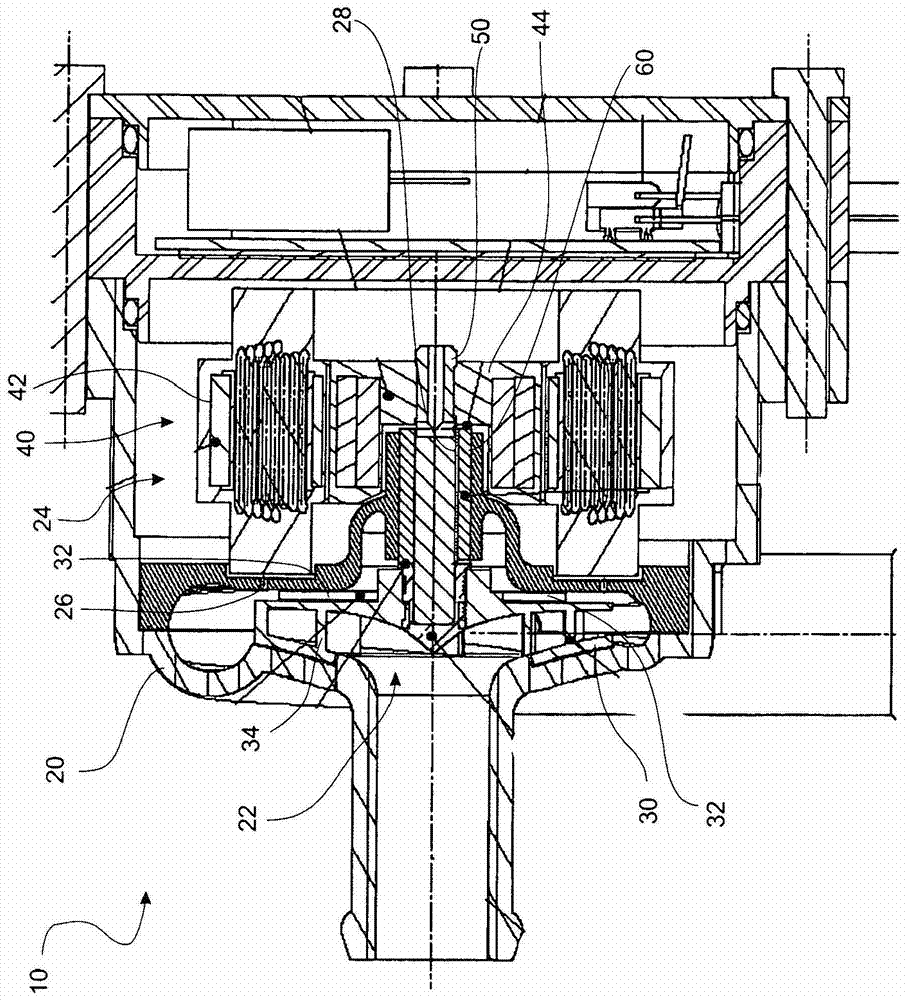
[0028] exist figure 1 An embodiment of a pump 10 according to the invention is schematically shown in . The pump 10 is provided with a housing 20 which has a pump chamber 22 and a motor chamber 24 formed in its interior. A motor 40 is formed in the motor chamber 24 , which is formed in the form of an electric motor in the present embodiment. The motor 40 is provided with a stator 42 inside which a rotor 44 rotates. The rotor 44 is connected rotationally torque-fittingly to the impeller 30 via a drive shaft 50 .

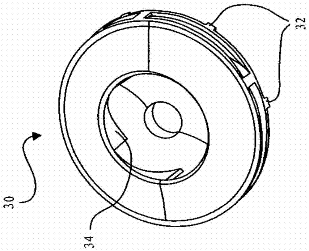
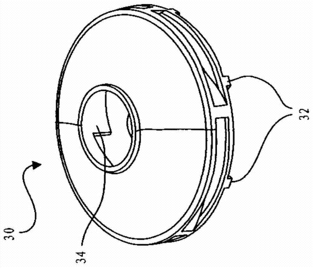
[0029] The impeller 30 is for example according to figure 2 , image 3 , Figure 4 or Figure 5 structure, which will be described in detail later. also, figure 1 The pump 10 according to the invention according to an embodiment of the present invention also has a suction connection which connects from the left to the suction side of the impeller 30 . Visible tangentially around the impeller 30 is a surrounding annular channel which serves for the output and...


PUM


Abstract

The invention relates to a pump (10) for a temperature circuit in a motor vehicle, the pump having a housing (20) with at least one pump chamber (22) and a power unit arranged in the pump chamber (22). A rotating impeller (30) for conveying fluids, wherein at least one flow member (32) is arranged on the impeller (30) for generating the following pressure field when the impeller (30) rotates , the pressure field is opposite to the pressure field generated by conveying the fluid.

Description

technical field [0001] The invention relates to a pump for a temperature circuit in a motor vehicle and to a temperature circuit with a pump for a motor vehicle. Background technique [0002] Pumps are known for temperature circuits, especially cooling circuits, in motor vehicles. Such pumps are frequently used as so-called rotary pumps, as they are known, for example, from DE 36 03 812 . In this case, such a pump has a housing with at least one pump chamber, wherein a rotatable impeller for conveying the fluid is arranged in the pump chamber. For this purpose, the impeller is designed as an open, partially closed or closed impeller, for example in the form of a rotary pump. In this rotary pump embodiment, the suction takes place centrally by the rotation of the impeller. On the peripheral side, in particular in the tangential direction, the conveyed fluid is discharged. In the tangential direction it can thus also be said to be on the pressure side and centrally on the ...

Claims


Application Information

Patent Timeline
Patent Type & Authority Patents(China)
IPC IPC(8): F04D13/06F04D29/22F04D29/42F04D29/04
CPCF04D29/2266
Inventor T·许泽N·托内曼
Owner 海拉有限双合股份公司
Why Eureka
Try Eureka