
Valve rod of multi-path valve and multi-path valve with valve rod

A multi-way valve and valve stem technology, which is applied to the valve stem of multi-way valve, hydraulic valve and multi-way valve field, can solve the problem of affecting the life of the seal and the overall performance of the whole machine, unstable movement of the oil cylinder, and the phenomenon of air suction of the oil cylinder cannot be eliminated. and other problems, to achieve the effect of improving energy utilization, good versatility and simple structure

Active Publication Date: 2013-06-05
ZHEJIANG HAIHONG HYDRAULIC TECH
View PDF6 Cites 8 Cited by
  • Summary
  • Abstract
  • Description
  • Claims
  • Application Information

AI Technical Summary

Problems solved by technology

[0005] The purpose of the present invention is to solve the above-mentioned problems in the existing technology, and propose a valve stem of a multi-way valve and a multi-way valve with the above-mentioned valve stem. The technical problem to be solved is: the oil cylinder of the existing multi-way valve The phenomenon of air suction cannot be eliminated, which will easily lead to unstable movement of the oil cylinder, which will affect the life of the seal and the overall performance of the whole machine

Method used


Image

  • Valve rod of multi-path valve and multi-path valve with valve rod
  • Valve rod of multi-path valve and multi-path valve with valve rod
  • Valve rod of multi-path valve and multi-path valve with valve rod

Examples


Embodiment Construction

[0029]The following are specific embodiments of the present invention and in conjunction with the accompanying drawings, the technical solutions of the present invention are further described, but the present invention is not limited to these embodiments.

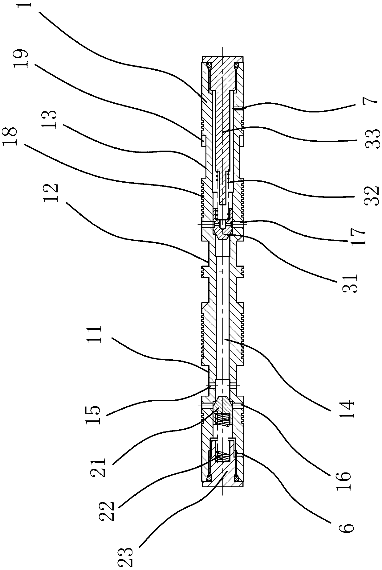
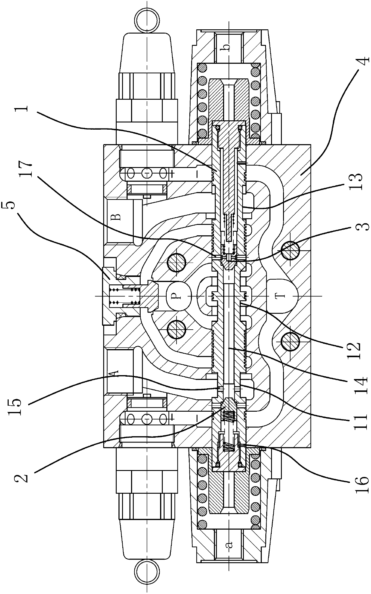
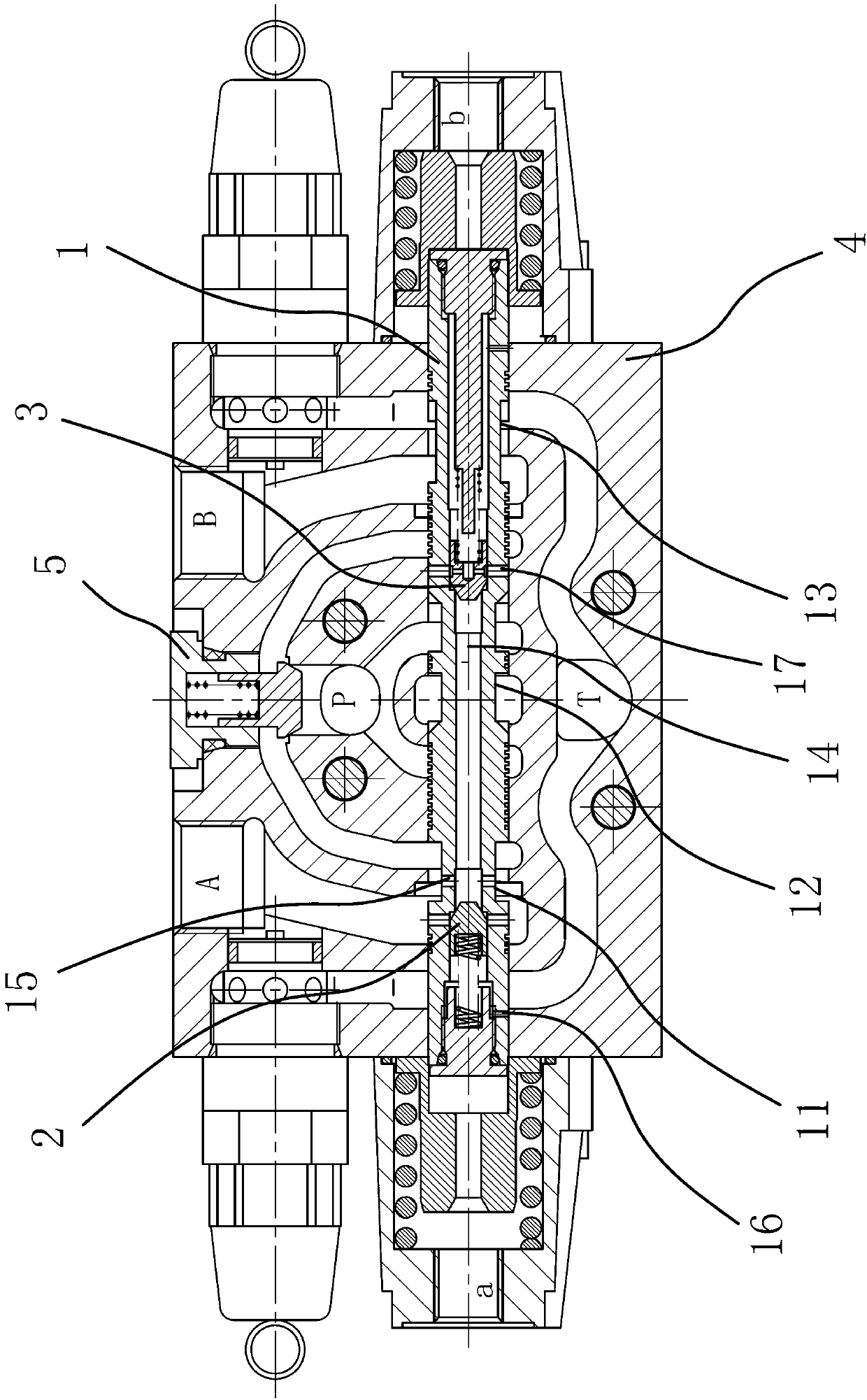
[0030] Such as figure 1 As shown, the valve stem of this multi-way valve includes a rod body 1, and the outer surface of the rod body 1 is sequentially provided with a communication groove 11, a communication groove 2 12 and a communication groove 3 13 from one end to the other end; hole 14. An oil inlet hole 15 communicating with the axial hole 14 is opened on the bottom surface of the first communication groove 11 . There is an oil return hole 16 connected to the axial hole 14 on the side between one end surface of the rod body 1 and the communication groove 11, and the rod body 1 is provided with a valve that can only make the hydraulic oil flow from the axial hole 14 to the oil return hole 16. One-way structure one 2....


PUM


Abstract

The invention provides a valve rod of a multi-path valve and the multi-path valve with the valve rod and belongs to the technical field of machinery. The valve rod and the multi-path valve solve the problem that the phenomenon of empty sucking of the existing multi-path cylinder cannot be eliminated, the cylinder is unstable in operation, and service life and integral performance of sealing members are influenced. The multi-path valve comprises a valve body and the valve rod arranged in the valve body, wherein an ascending working cavity, a descending working cavity, an oil inlet cavity and an oil return cavity are arranged in the valve body, a first guide assembly with an ascending guide opening and corresponding to one end of the valve rod is arranged on the valve body, and a second guide assembly with a descending guide opening and corresponding to the other end of the valve rod is arranged on the valve body; and by means of a first communication groove, a second communication groove and a third communication groove on the valve rod, the ascending working cavity can be communicated with the oil inlet cavity, the oil inlet cavity can be communicated with the oil return cavity, and the descending working cavity can be communicated with the oil return cavity or the oil inlet cavity. The multi-path valve can achieve energy recovering during descending of the oil cylinder, avoids the phenomenon of empty sucking of the descending working cavity caused by fast descending of the oil cylinder and prolongs service life of the oil cylinder.

Description

technical field [0001] The invention belongs to the technical field of engineering components, and relates to a hydraulic valve, in particular to a valve stem of a multi-way valve. [0002] The invention belongs to the technical field of engineering components, and relates to a hydraulic valve, in particular to a multi-way valve. Background technique [0003] A multi-way valve is a combination of more than two valve blocks to manipulate the movement of multiple actuators. Because it can combine various valves according to the requirements of different hydraulic systems, it has compact structure, simple pipeline, small pressure loss and convenient installation, so it is widely used in construction machinery, lifting and transportation machinery and other operations requiring multiple operations. Walking machinery and other fields where an actuator moves. In the field of construction machinery, such as excavators, loaders, forklifts and other working cylinders are in the pro...

Claims


Application Information

Patent Timeline
Patent Type & Authority Applications(China)
IPC IPC(8): F15B13/02
Inventor 何贤剑杨济铭
Owner ZHEJIANG HAIHONG HYDRAULIC TECH
Learn More