Cable bridge frame cover plate

A technology for cable trays and cover plates, which is applied in the direction of pipe supports, pipes/pipe joints/fittings, mechanical equipment, etc. It can solve problems such as unfavorable cable laying, unsightly appearance, and affecting construction, and achieves benefits for cable laying construction and shape design. Novelty, the effect of increasing the effective space

Inactive Publication Date: 2013-06-05
JIANYE QINGSONG GROUP
View PDF0 Cites 3 Cited by
  • Summary
  • Abstract
  • Description
  • Claims
  • Application Information

AI Technical Summary

Problems solved by technology

[0002] Cable trays are widely used in power engineering. The original cable tray cover plate is a planar structure. In actual engineering applications, it is found that the structure cover plate has the following defects: 1. The mechanical strength is weak and easy to deform
In particular, after long-distance transportation, the cover plate is severely deformed at the construction site, and cannot be installed on the bridge frame at one time, and it must be repaired on site.
2. It does not meet the requirements of load-bearing mechanics. When the bridge cover is covered with thick snow in winter in the north, it is easy to deform
When maintenance is required, the cover is often stuck, making it difficult to remove and install
3. It is not conducive to drainage, and the phenomenon of water collection is serious when deformation occurs
4. The space inside the bridge is narrow, which is not conducive to cable laying and affects the construction. When the diameter of the cable is large, the turning of the cable will be upturned, and the flat cover plate cannot effectively cover the bridge.
The narrow space is also not conducive to the heat dissipation of the cable, which affects the performance and life of the cable
5. Outdated appearance, not beautiful, not in harmony with the environment

Method used


Image

  • Cable bridge frame cover plate
  • Cable bridge frame cover plate

Examples


Embodiment Construction

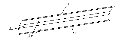
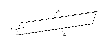
[0011] The present invention includes a cover top surface arranged in a certain radian and a cover vertical surface 3 arranged on both sides of the cover top surface; the cover top surface of the present invention includes a cover plane 1 and a cover plane 1 and a cover plate Between the vertical surfaces 3 is the cover plate slope 2 that connects the cover plate plane 1 and the cover plate vertical surface 3 and is arranged obliquely downward.

[0012] The cover plate slope 2 of the present invention is arranged symmetrically.

[0013] The present invention is especially suitable for long-distance laying of cables, and when large-diameter cables are bent and laid, or when there are many cables in the bridge frame, the advantages of the present invention will be more prominent.


PUM


Abstract

The invention relates to a cable bridge frame cover plate. The cable bridge frame cover plate comprises a cover plate top surface which is arranged in a certain radian and a cover plate vertical surface which is arranged on two sides of the cover plate top surface. The cable bridge frame cover plate has the advantages that: (1) mechanical strength is high, the cable bridge frame cover plate is not easy to deform, (2) drainage condition is met, drainage is unobstructed in a rainy weather, a catchment phenomenon can not occur, (3) loading mechanical requirements are met, when thick accumulated snow covers the bridge frame cover plate in north and winter, pressure of the accumulated snow to the cover plate can be effectively reduced, (4) effective space in the bridge frame is increased, the cable bridge frame cover plate is beneficial for cable laying construction and cable heat dissipation, and (5) the cable bridge frame cover plate is novel in shape design, more attractive and more harmonious with the environment.

Description

technical field [0001] The invention relates to a cable bridge cover plate, which is applied in the technical field of electric power engineering. Background technique [0002] Cable trays are widely used in electric power engineering. The original cable tray cover plate is a planar structure. In practical engineering applications, it is found that the structure cover plate has the following defects: 1. The mechanical strength is weak and it is easy to deform. In particular, after long-distance transportation, the cover plate is severely deformed at the construction site, and cannot be installed on the bridge frame at one time, and it must be repaired on site. 2. It does not meet the requirements of load-bearing mechanics. When the bridge cover is covered with thick snow in winter in the north, it is easy to deform. When maintenance is required, the cover plate is often stuck, making it difficult to remove and install. 3. It is not conducive to drainage, and the phenomenon...

Claims


Application Information

Patent Timeline
Patent Type & Authority Applications(China)
IPC IPC(8): F16L3/00
Inventor 薛明琪陶强潘志斌
Owner JIANYE QINGSONG GROUP
Why Eureka
Try Eureka