Lighting source detection machine and detection method

A lighting source and detection method technology, which is applied in the direction of lamp testing and optical performance testing, can solve problems such as detection omissions, error-proneness, and improvement, and achieve accurate detection operations, reduce omissions, and improve detection efficiency.

Inactive Publication Date: 2013-06-05
致茂电子(苏州)有限公司
View PDF5 Cites 9 Cited by
  • Summary
  • Abstract
  • Description
  • Claims
  • Application Information

AI Technical Summary

Problems solved by technology

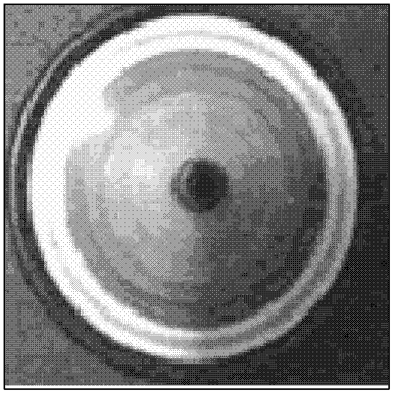
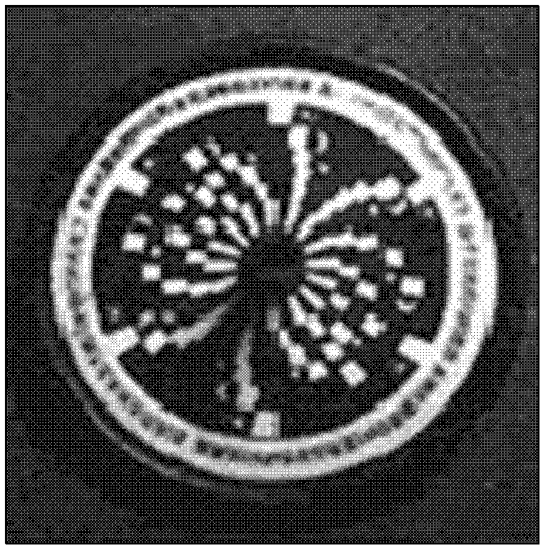
If during the rotation, the light emitted by the LED under test is as follows figure 2 The stable halo pattern and color phenomenon shown indicate that the current LED to be tested has no obvious stroboscopic problem in the human visual sensitivity range, and will not form a strong stroboscopic effect; on the contrary, if it is observed from the surface of the gyro like image 3 The multiple patterns with different colors are shown, and each halo will show rich changes in rotation direction, rotation speed and color with the change of the rotation speed of the gyroscope, which means tha

Method used


Image

  • Lighting source detection machine and detection method
  • Lighting source detection machine and detection method
  • Lighting source detection machine and detection method

Examples


Embodiment Construction

[0046] The aforementioned and other technical contents, features and effects of the present invention will be clearly presented in the following detailed description of preferred embodiments with accompanying drawings.

[0047] A preferred embodiment of the lighting source detection machine of the present invention is as follows: Figure 4 , Figure 5 and Image 6 As shown, it mainly includes a base 41, a wide-area dynamic light detection device 42, a processing device 43, an enabling conveyor 44 and a classification device 45, wherein the wide-area dynamic light detection device 42 includes a plurality of solar cells 421, resulting in The energy conveyor 44 is arranged on the base 41, and includes a feeding arm 441 and a conveyor belt 443, and the sorting device 45 further includes a sorting arm 451, which can be picked and placed through the feeding arm 441 and the sorting arm 451. Components are transferred, and the lighting source to be tested can be LED, cold-cathode tu...


PUM


Abstract

Disclosed are a lighting source detection machine and a lighting source detection method. The lighting source detection machine includes a base, a wide-area dynamic optical detection device, a processing device, a driving conveyor and a sorting device, wherein the wide-area dynamic optical detection device includes a plurality of solar cells, and the driving conveyor includes a feeding arm and a conveying belt. The detection method includes that the feeding arm draws a lighting source of an illustrated LED (light-emitting diode) and transfers the lighting source on the conveying belt, the conveying belt conveys the plurality of lighting sources to be detected to detection positions on the base and supplies power to drive the lighting sources to shine, the solar cells receive optical signals, transfer the optical signal into electric signals, and transmit the electric signals to the processing device to perform Fourier transform, Fourier reverse transform after noise signals are removed, and stroboscopic and stroboscopic effect detections, and finally the processing device drives the sorting device to sort every LED.

Description

【Technical field】 [0001] The invention relates to a detection of stroboscopic and stroboscopic effects of an illumination light source, in particular a detection machine and detection method for an illumination light source. 【Background technique】 [0002] With the evolution of science and technology, the use of LEDs as lighting equipment continues to innovate, and product performance continues to be continuously improved. However, due to unstable power supply, the luminous intensity of the light source changes with time, the circuit design and the unreasonable design of the lighting device. The emitted light produces periodic and non-periodic flickering of luminous intensity; and this kind of flicker, once in the frequency range that can be perceived by human vision, will cause discomfort, fatigue, and even damage to rotating objects due to the flickering of the light source. Misjudgment of the speed of rotation can lead to accidents and injuries. Therefore, when the fluct...

Claims


Application Information

Patent Timeline
IPC IPC(8): G01R31/44G01M11/02
Inventor 翁思渊陈思伟陈忞圣
Owner 致茂电子(苏州)有限公司
Why Eureka
Try Eureka