Laser radar system with function of inhibiting low-altitude strong echo signals

A technology of laser radar and strong echo, which is applied in the direction of radio wave measurement systems and instruments, can solve the problem of signal uncertainty and achieve the effect of avoiding signal distortion

Inactive Publication Date: 2013-06-05
ANHUI INST OF OPTICS & FINE MECHANICS - CHINESE ACAD OF SCI
View PDF2 Cites 5 Cited by
  • Summary
  • Abstract
  • Description
  • Claims
  • Application Information

AI Technical Summary

Problems solved by technology

At this time, the photomultiplier tube is easy to be saturat

Method used


Image

  • Laser radar system with function of inhibiting low-altitude strong echo signals
  • Laser radar system with function of inhibiting low-altitude strong echo signals

Examples


Embodiment 1

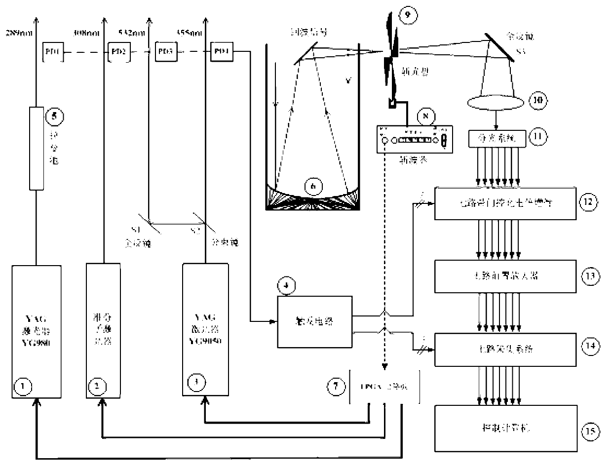
[0025] Detection of stratospheric ozone. Such as figure 2After all the preparations are completed, under normal operation conditions, first set the working voltage of 8 so that the output frequency is 200Hz, and 9 starts to rotate at the same time, after the 9 speed is constant and the 8 output frequency is maintained at 200Hz, turn on the lasers 2 and 3, The synchronous frequency signal output by 8 is connected to 7, and after 7, two alternate 50Hz pulse trigger signals are generated to control 2, 3, 2, and 3 to alternately emit lasers of corresponding wavelengths into the atmosphere. On the emission optical path, the scattered light of the laser is The PD placed on the side of the optical path receives, and the PD is converted into an electrical signal and input to 4, and 4 triggers the signal to trigger the acquisition system 14 and trigger the gating of the photomultiplier tube 12. 6. Pass the received echo signal through 9 and then pass through 10, 11, 12, 13, 14 in tur...

Embodiment 2

[0027] Detection of tropospheric ozone. Such as figure 2 , After all preparations are completed, under normal operation conditions, first set the working voltage of 8 to make its output frequency 200Hz, and 9 starts to rotate at the same time, after the 9 speed is constant and the 8 output frequency is maintained at 200Hz, turn on the lasers 1 and 2, The synchronous frequency signal output by 8 is connected to 7, and after 7, 2 alternate 20Hz pulse trigger signals are generated to control 1, 2, 1, and 2 to alternately emit lasers of corresponding wavelengths into the atmosphere. On the emission optical path, the scattered light of the laser is The PD placed on the side of the optical path receives, and the PD is converted into an electrical signal and input to 4, and 4 triggers the signal to trigger the acquisition system 14 and trigger the gating of the photomultiplier tube 12. 6. Pass the received echo signal through 9 and then pass through 10, 11, 12, 13, 14 in turn, and ...


PUM


Abstract

The invention discloses a laser radar system with a function of inhibiting low-altitude strong echo signals. Frequency signals are output through an optical chopper to serve as synchronizing signals, external triggering signals of lasers are generated through signal processing of a field programmable gate array (FPGA) circuit board, low-altitude atmosphere echo signals are enabled to be shielded by a solid area of a chopping plate on the optical chopper for a certain period of time (in the process of detecting atmospheric composition of the stratosphere) by adjusting the laser emitting time of lasers, the strong echo signals are physically shielded from directly being emitted on a light sensing surface of a photomultiplier, the photomultiplier is prevented from having the phenomena of saturation and fatigue when a door is opened and closed, the FPGA circuit board receives synchronizing frequency signals output by the optical chopper, and the external triggering signals, meeting the work requirements of the lasers, of three lasers are generated under the action of the synchronizing frequency signals. According to different combinations among the lasers, the laser radar system with the function of inhibiting low-altitude strong echo signals can detect ozone, water vapor and aerosol in the troposphere, can detect ozone in the stratosphere and the aerosol in the stratosphere, and can effectively inhibit the low-altitude strong echo signals.

Description

technical field [0001] The invention relates to the field of laser radar systems, in particular to a laser radar system capable of suppressing low-altitude strong echo signals. Background technique [0002] Lidar is a high-tech precision instrument integrating opto-mechanical electronics, which is mostly used for quantitative detection of atmospheric parameters. Some lidars are measuring high-level (such as the stratosphere) atmospheric ozone, atmospheric aerosols, water vapor, etc., using a gated photomultiplier tube (a device that converts weak atmospheric echo signals into weak electrical signals), through Adjust the delay time for triggering the gate control of the photomultiplier tube to adjust the measurement range, and at the same time discard the low-altitude strong echo signal. However, during the gating adjustment process, there will still be a strong echo signal in the switching transition area of ​​the gating, which will cause smearing due to the inability to r...

Claims


Application Information

Patent Timeline
IPC IPC(8): G01S7/48G01S7/481
Inventor 黄见胡顺星曹开法孟祥谦苑克娥
Owner ANHUI INST OF OPTICS & FINE MECHANICS - CHINESE ACAD OF SCI
Why Eureka
Try Eureka