
Array type focusing mirror with high utilization rate

A utilization rate and array technology, applied in the field of array focusing mirrors, can solve the problems of reduced focusing magnification, large light spot, large energy loss, etc., to simplify manufacturing requirements, reduce manufacturing costs, and improve the effect of focusing effect.

Inactive Publication Date: 2013-06-05
陕西科林能源发展股份有限公司
View PDF0 Cites 0 Cited by
  • Summary
  • Abstract
  • Description
  • Claims
  • Application Information

AI Technical Summary

Problems solved by technology

When multi-mirror tracking and focusing, the reflection line is usually not parallel to the optical axis of the reflector, resulting in a large spot, which reduces the focusing magnification, resulting in a large energy loss during heat utilization

Method used


Image

  • Array type focusing mirror with high utilization rate
  • Array type focusing mirror with high utilization rate
  • Array type focusing mirror with high utilization rate

Examples


Embodiment Construction

[0009] The implementation of the present invention will be described in detail below in conjunction with the drawings and examples.

[0010] For the high-utilization array focusing mirror of the present invention, the section of the high-utilization array focusing mirror can be a plane, a paraboloid, a quadric surface including a spherical surface, or a combination thereof. A plurality of array focusing reflectors with the same smaller area and the same high utilization rate replaces a variety of condensers with a larger area, which simplifies the manufacturing requirements of the condenser, reduces the manufacturing cost of the condenser, and improves the light-condensing effect of the condenser.

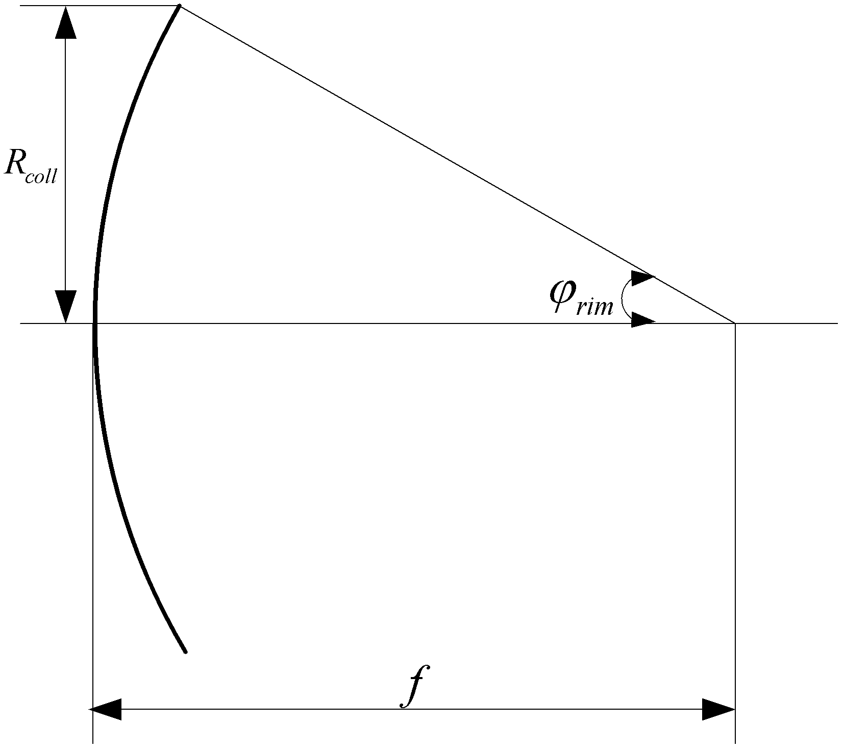
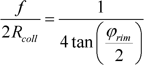
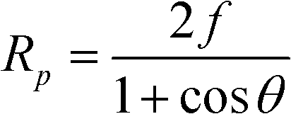
[0011] As shown in the figure, the focal length f is the distance from the center point of the paraboloid to the focal plane, the opening radius Rcoll is the distance from the edge of the mirror to the axis, and the edge angle is the angle between the focal point and the edge of t...


PUM


Abstract

The invention is an array type focusing mirror with high utilization rate. The section of the array type focusing mirror with high utilization rate is a plane, a paraboloid, a quadric surface including a spherical surface or any combination thereof. As a collecting lens of any kind with a relatively great area is replaced by multiple same array type focusing mirrors with high utilization rate and relatively small areas, the array type focusing mirror with high utilization rate simplifies manufacturing requests on the collecting lens, lowers manufacturing cost of the collecting lens and also improves the light collecting effect of the collecting lens.

Description

technical field [0001] The invention relates to an array type focusing reflector with high utilization rate. Background technique [0002] The world's energy sources are depleting day by day, and the development and utilization of renewable energy have broad prospects. The comprehensive and efficient use of solar energy is the goal pursued by relevant people. Due to the low density of solar energy, the use of concentrated light can increase the density of solar energy, thereby improving the efficiency of solar energy utilization, which is one of the main methods of solar energy utilization. At present, the concentrated solar energy utilization system mainly includes a point concentration system with multiple reflectors tracking sunlight, such as a tower solar thermal power generation system; a reflective parabolic line focusing solar energy utilization system with a tracking device; a butterfly parabolic focusing system with a tracking device Solar energy utilization system...

Claims


Application Information

Patent Timeline
Patent Type & Authority Applications(China)
IPC IPC(8): G02B19/00
Inventor 杨向民李琥
Owner 陕西科林能源发展股份有限公司
Learn More