Gear drive mechanism of rotating shaver

A technology of gear transmission mechanism and shaver, which is applied in the direction of gear transmission, transmission, belt/chain/gear, etc. It can solve the problems of gears not meshing normally, short service life, high production cost, etc., and achieve simplified manufacturing and assembly Process requirements, improve product quality, long service life

Active Publication Date: 2012-11-21
SHANGHAI FLYCO ELECTRICAL APPLIANCE
View PDF0 Cites 0 Cited by
  • Summary
  • Abstract
  • Description
  • Claims
  • Application Information

AI Technical Summary

Problems solved by technology

Although this solution solves the problem of the angle between the plane of the razor unit and the handle, because the installation position of the bevel gear is much higher than that of the cylindrical gear, the cone tops of the two gears must overlap in addition to the angle requirements, otherwise the gears cannot mesh normally. When the noise is high, the gears will wear out rapidly, and the mechanism will fail quickly. Therefore, the requirements for product production and assembly are very high, resulting in low product yield, high production costs, and short service life.
In addition, the electric shaver is a high-speed rotating mechanism (the output speed of the motor is about 8000rpm), and the parts are plastic products. The manufacturing precision and installation technical requirements of the bevel gear and the gear frame have far exceeded the economic precision range of plastic products, and the operation of the device is stable. , instantaneous speed ratio, and noise level are difficult to meet the economic and technical requirements
So so far, there is no gear transmission mechanism that can solve the above problems well.

Method used


Image

  • Gear drive mechanism of rotating shaver
  • Gear drive mechanism of rotating shaver
  • Gear drive mechanism of rotating shaver

Examples


specific Embodiment 1

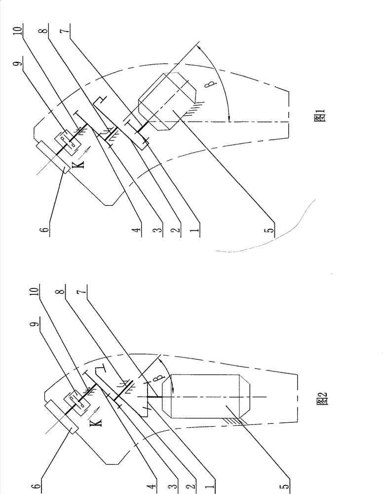
[0014] Specific embodiment 1: the gear transmission mechanism of the rotary shaver is to comprise the gear transmission mechanism between the driving gear installed on the motor shaft, at least one half coupling, the driving gear and the half coupling, the driving gear, the driving The gear transmission mechanism between the gear and the half-coupling is composed of at least one cylindrical bevel gear and several cylindrical gears. The sum of the included angles formed by the axis of the cylindrical bevel gear and the axis of the meshing cylindrical gear in each transmission stage is equal to the axis of the handle. (that is, the axis of the motor) and the angle requirements between the axis of the razor group. Cylindrical bevel gears are bevel gears that can mesh with involute cylindrical gears. The forming principle of the tooth profile is that under the condition that the two axes of the gear shaper and the bevel gear blank intersect and form a set angle, the involute gear i...

specific Embodiment 2

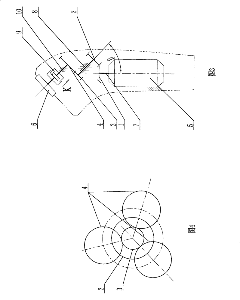
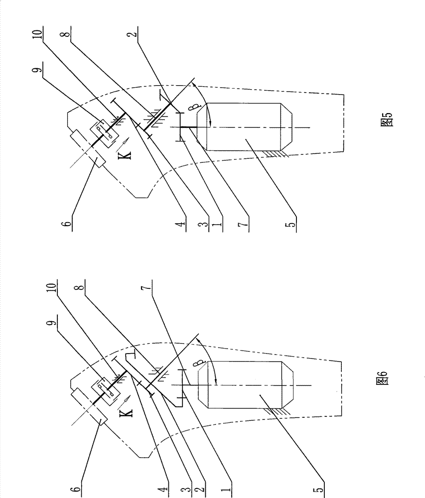
[0015] Specific embodiment 2: as Figure 6 As shown, the gear transmission mechanism of the rotary shaver is provided with a first driving gear 1, a first driven gear 2, a second driving gear 3 and three second driven gears 4, wherein the first driven gear The gear 2 adopts an inner cylindrical bevel gear, and its taper is determined by the angle β between the axis of the motor 5 and the razor group 6 axes. The first driving gear 1 adopts a cylindrical gear to be arranged on the motor shaft 7, and the first driven gear 2 and the second driving gear 3 form a duplex gear and are arranged at both ends of the first driven shaft 8, and the first driven shaft 8 and the The motor shaft 7 is installed obliquely, the angle is the angle between the two axes (that is, the set angle β) described in the tooth profile forming principle of the cylindrical bevel gear, the axis of the motor 5 is vertically arranged, along the axis of the first driven shaft 8 Direction The first driven wheel 2...


PUM


Abstract

The invention relates to a gear drive mechanism for rotary-type razors, which comprises a driving gear arranged on a motor shaft, as well as a gear drive mechanism between the driving gear and a half-coupling. The mechanism is characterized in that the driving gear and the gear drive mechanism between the driving gear and the half-coupling consist of a cylindrical bevel gear and a plurality of cylindrical gears; the cylindrical bevel gear is a bevel gear capable of meshing with an involute cylindrical gear; the forming principle of a tooth profile of the cylindrical bevel gear is to obtain a conjugate tooth profile by using an involute gear slotting tool to perform generating machining to a bevel gear blank under the conditions that a gear shaping tool and two axes of the gear blank intersect and are at a set included angle. The drive mechanism has the advantages of greatly simplifying technological requirements on manufacture and assembly, reducing cost, improving product quality andwell solving problems existing in the prior art, along with low noise and long life span.

Description

technical field [0001] The invention relates to a gear transmission mechanism of a rotary shaver. Background technique [0002] The gear transmission mechanism ( figure 1 ) usually includes a spur gear z 1 ,z 2 ,z 3 ,z 4 gear train, drive gear z 1 Installed on the motor shaft, the gear z 2 and gear z 3 It is a double gear, the driving gear z 1 drive gear z 2 , gear z 3 drives three gears z with the same function 4 And it drives three razor groups to work at the same time through the coupling elastically combined with it to realize the shaving function. Because this kind of gear transmission mechanism is meshed with cylindrical gears, the axis of the motor is parallel to the axis of the razor unit. Most of the time when using it, the wrist and elbow need to rotate upwards by 30-60°. Therefore, the handle is designed for the comfort of use. (that is, the body) and the position of the razor unit, it is required that the razor unit and the centerline of the handle (i...

Claims


Application Information

Patent Timeline
Patent Type & Authority Patents(China)
IPC IPC(8): F16H1/20F16H1/22F16H55/08B26B19/28
Inventor 李丐腾
Owner SHANGHAI FLYCO ELECTRICAL APPLIANCE
Why Eureka
Try Eureka