
Decomposition calculating method of optimal power flow of power system with unified power flow controller

A technology of power flow controller and optimal power flow, which is applied in the direction of AC network circuits, electrical components, circuit devices, etc., can solve problems such as nonlinear enhancement, poor system convergence and reliability, and large amount of calculation, so as to improve efficiency and reliability, simplification of optimized calculations, the effect of excellent computing performance

Inactive Publication Date: 2013-06-05
SHENYANG POLYTECHNIC UNIV
View PDF3 Cites 32 Cited by
  • Summary
  • Abstract
  • Description
  • Claims
  • Application Information

AI Technical Summary

Problems solved by technology

There are three main problems in these methods at this stage. First, the control equation of the unified power flow controller is introduced, which increases the nonlinearity of the solution problem, so the convergence and reliability of the system become worse; the optimal power flow problem of the power system itself is a problem. For high-dimensional large-scale system optimization problems with strong nonlinearity, after the introduction of the unified power flow controller control equation, it is optimized and solved together with the original equations of the power system. The nonlinearity of the problem is further strengthened, and the convergence and Reduced reliability
The second is that after adding the new control equations, the original algorithms and programs need to be greatly modified; the third is that the existing optimization power flow algorithms and programs are not fully utilized
Because this kind of method optimizes and solves the control parameters of the system and the control parameters of the unified power flow controller together, the scale of the optimization solution problem is very large, and the amount of calculation is huge, so it cannot be practical

Method used


Image

  • Decomposition calculating method of optimal power flow of power system with unified power flow controller
  • Decomposition calculating method of optimal power flow of power system with unified power flow controller
  • Decomposition calculating method of optimal power flow of power system with unified power flow controller

Examples


Embodiment Construction

[0066] The features, advantages and implementation modes of the present invention will be described in further detail below in conjunction with the accompanying drawings and calculation examples.

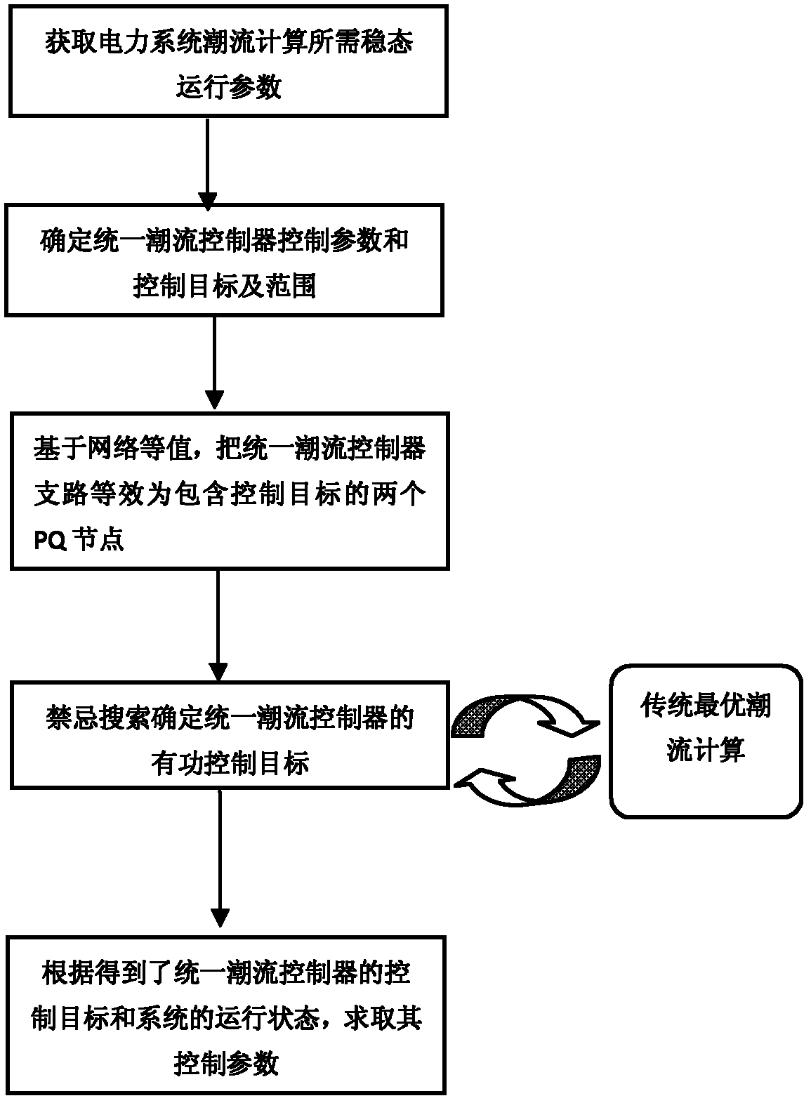
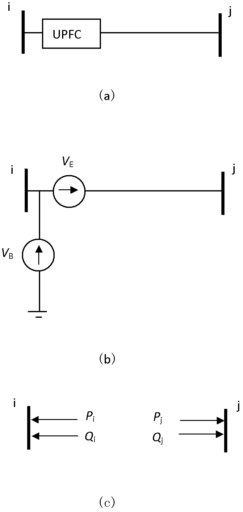
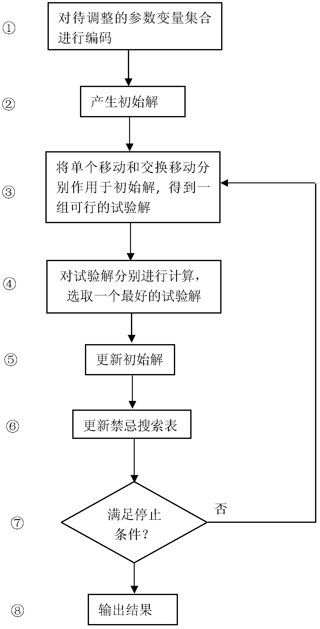
[0067] Such as figure 1 , figure 2 , image 3 , Figure 4 As shown in , a method for decomposing and calculating the optimal power flow of a power system including a unified power flow controller includes the following steps:

[0068] Step 1) Obtain the steady-state operating parameters required for the optimal power flow calculation of the power system;

[0069] Step 2) Determine the control parameters, control objectives and control range of the unified power flow controller

[0070] Step 3) Based on network equivalence, the branches of the unified power flow controller are equivalent to two PQ nodes containing control targets

[0071] Step 4) Using tabu search, the optimal power flow calculation is performed multiple times to determine the active power control target of the...


PUM


Abstract

Disclosed is a decomposition calculating method of the optimal power flow of a power system with a unified power flow controller. The method is characterized by comprising the following steps of firstly obtaining steady-state operating parameters required by the power flow calculation of the power system; secondly, determining the mounting position and the control parameter range of the unified power flow controller; thirdly, based on network equivalence, equalizing the branches of the unified power flow controller to two PQ nodes containing control targets; fourthly, utilizing taboo research to perform multiple optimal power flow calculation to determine an active control target of the unified power flow controller; and fifthly, calculating the control parameters according to the obtained control target of the unified power flow controller and the operation state of the system. The decomposition calculating method of the optimal power flow system with the unified power flow controller can equivalently decompose the optimal power flow calculation problem of the power system with the unified power flow controller into a two-layer optimization problem through network, can perform the optimal power flow calculation of the power system more effectively and more reliably, and has engineering use value.

Description

technical field [0001] The invention relates to a power system calculation method, in particular to a power system optimal power flow decomposition calculation method including a unified power flow controller, and belongs to the technical field of power system power transmission and operation. Background technique [0002] The safe and economical operation of modern power systems is facing new challenges, and the transmission network urgently needs new control methods to meet the needs of power transmission and operation in new forms. How to effectively adjust and control the power flow of the transmission network is one of the main problems that need to be solved urgently. There will be more flexible control devices put into operation in the power system, and a set of advanced, reliable and effective optimal power flow control methods must be adapted to meet the actual operation needs of the power system in the new form. It is of great practical significance to study the o...

Claims


Application Information

Patent Timeline
IPC IPC(8): H02J3/00
Inventor 叶鹏武智慧关多娇何柳袁林
Owner SHENYANG POLYTECHNIC UNIV
Learn More