
Micromotor rotor

A micro-motor and rotor technology, applied in the direction of magnetic circuit rotating parts, magnetic circuit shape/style/structure, etc., can solve the problems of increasing motor vibration and noise, poor rotor dynamic balance, affecting motor performance, etc., to ensure uniformity Effect

Inactive Publication Date: 2013-06-05
陈朝辉
View PDF0 Cites 1 Cited by
  • Summary
  • Abstract
  • Description
  • Claims
  • Application Information

AI Technical Summary

Problems solved by technology

[0003] The traditional multi-pole magnet rotor is made by bonding multiple magnets, but it is difficult to process when making a small micro-motor. At the same time, it is difficult to make the magnetic pole angle accurately due to the splicing of multiple magnetic blocks.
At the same time, because it is difficult to achieve uniform mass of the entire rotor during splicing, the dynamic balance of the rotor is poor, which increases the vibration and noise of the motor and affects the performance of the motor.

Method used


Image

  • Micromotor rotor
  • Micromotor rotor

Examples


Embodiment Construction

[0013] The present invention will now be further described in conjunction with specific examples, and the following examples are intended to illustrate the present invention rather than further limit the present invention.

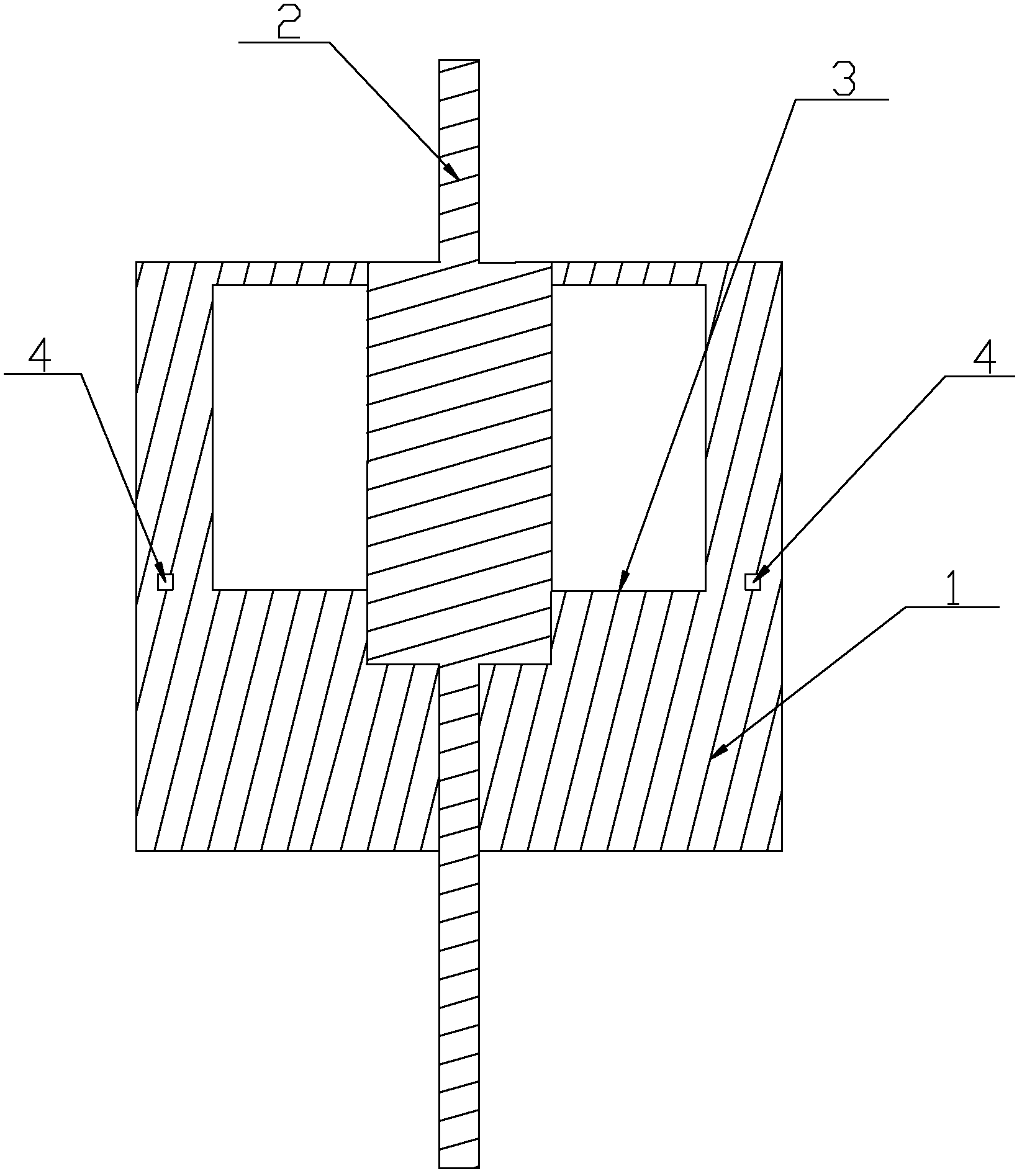
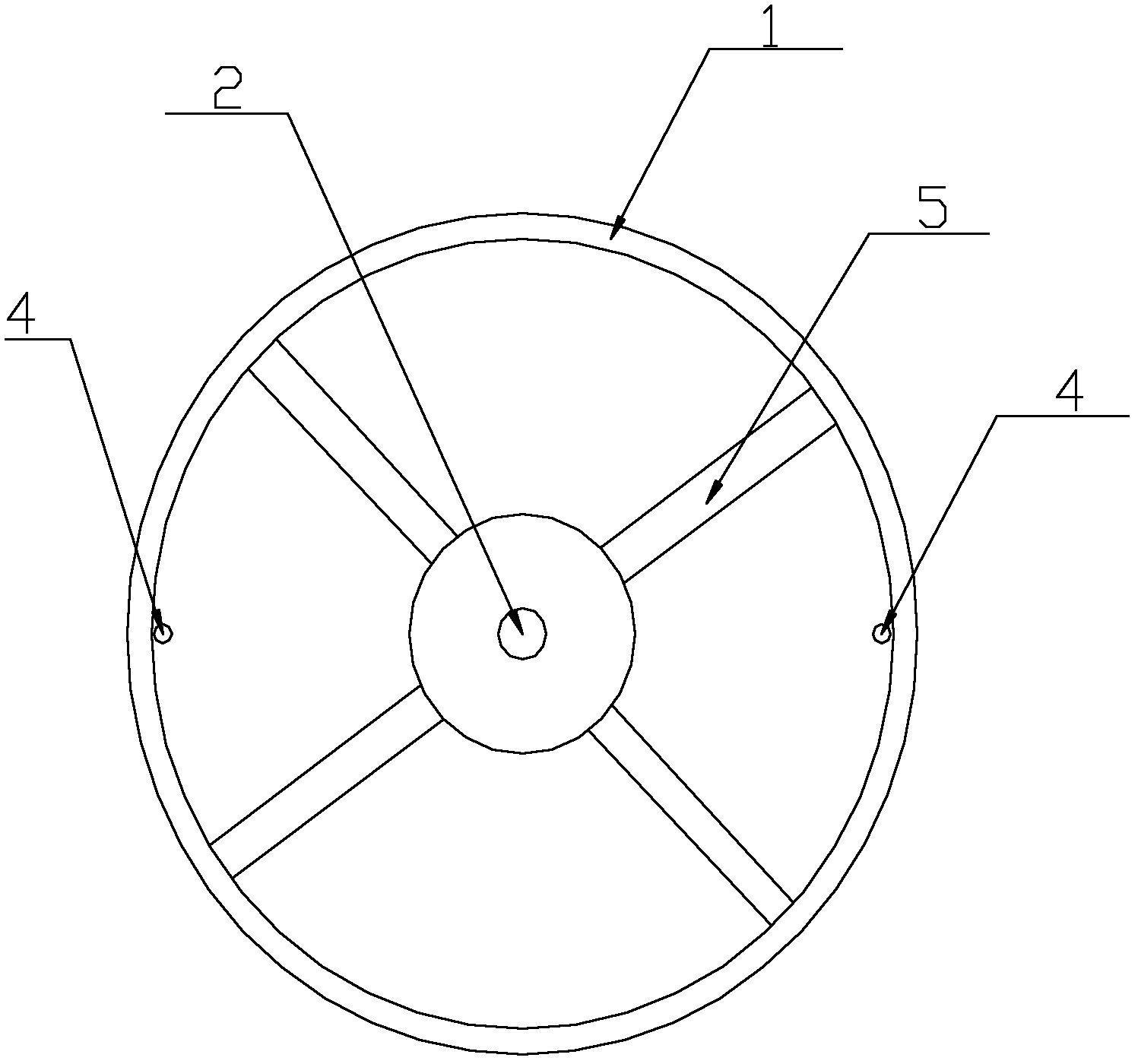
[0014] Such as Figure 1~2 The micro-motor rotor shown includes an integrated injection-molded plastic magnetic ring 1 and a rotating shaft 2 embedded in the magnetic ring. The magnetic ring 1 is an integral structure formed by injection molding of magnetic materials. The surface of the magnetic ring 1 is injected with a plurality of magnetic poles. The magnetic poles are evenly arranged in the magnetic ring 1 according to the reversed polarity. The magnetic ring 1 is connected with an end face 3. There are two opposite circular holes 4 on the end face 3. The rotating shaft 2 on the upper part of the end face 3 is connected to the magnetic ring 1. The inner wall is provided with reinforcing ribs 5 .

[0015] The magnetic ring 1 is a cylindrical structure....


PUM


Abstract

The invention relates to the technical field of motors and particularly relates to a micromotor rotor. The micromotor rotor comprises a plastic magnet ring and a rotating shaft, wherein the plastic magnet ring is subjected to integrated injection molding, the rotating shaft is embedded inside the magnet ring, the magnet ring is an integrated structure formed by injection molding of magnetic materials, a plurality of magnetic poles are injected on the surface of the magnetic ring, magnetic poles are uniformly arranged inside the body of the magnet ring in the sequence of reversed polarities, an end face is connected inside the magnet ring, two round holes which are arranged oppositely are arranged on the end face, and a reinforcing rib is arranged from the position of the rotating shaft on the upper portion of the end face to the position of the inner wall of the magnet ring. The rotor is formed once with magnetic materials, the rotating shaft serves as an insert during once molding, the concentricity of the rotor and the uniformity of the quality can be guaranteed, and simultaneously, the plurality of magnetic poles are injected at the same time of molding, so that the produced magnet rotor is provided with a multipole magnetic field.

Description

technical field [0001] The invention relates to the technical field of motors, in particular to a micro-motor rotor. Background technique [0002] Micro motors are now widely used in automation, electromechanical and other fields. Multi-pole magnetic rings are widely used as rotors in the fields of micro-motors and stepping motors. After a pulse current is passed through the external coil, the rotor rotates through a fixed angle. [0003] The traditional multi-pole magnet rotor is made by bonding multiple magnets, but it is difficult to process when making a small micro-motor. At the same time, it is difficult to make the magnetic pole angle accurately due to the splicing of multiple magnetic blocks. At the same time, because it is difficult to achieve uniform quality of the entire rotor during splicing, the dynamic balance of the rotor is poor, which increases the vibration and noise of the motor and affects the performance of the motor. Contents of the invention [000...

Claims


Application Information

Patent Timeline
Patent Type & Authority Applications(China)
IPC IPC(8): H02K1/27
Inventor 陈朝辉
Owner 陈朝辉
Learn More