
A virtual network and construction method for realizing traffic isolation control

A virtual network and traffic technology, applied in the field of virtual network management, can solve the problems of complex management and contention for traffic, and achieve the effect of simple management, reduced configuration requirements, and simple configuration

Inactive Publication Date: 2016-07-13
OPZOON TECH
View PDF3 Cites 0 Cited by
  • Summary
  • Abstract
  • Description
  • Claims
  • Application Information

AI Technical Summary

Problems solved by technology

[0007] This solution can basically solve some problems and reduce the requirements on the server, but the administrator needs to manually configure different servers separately, which makes the management complicated
If the number of server network cards is consistent, a unified network configuration interface can indeed be provided, but this puts forward new requirements for hardware configuration
In addition, it does not provide a good isolation mechanism for different types of traffic, and there will still be problems of competing for traffic

Method used


Image

  • A virtual network and construction method for realizing traffic isolation control
  • A virtual network and construction method for realizing traffic isolation control
  • A virtual network and construction method for realizing traffic isolation control

Examples


Embodiment 1

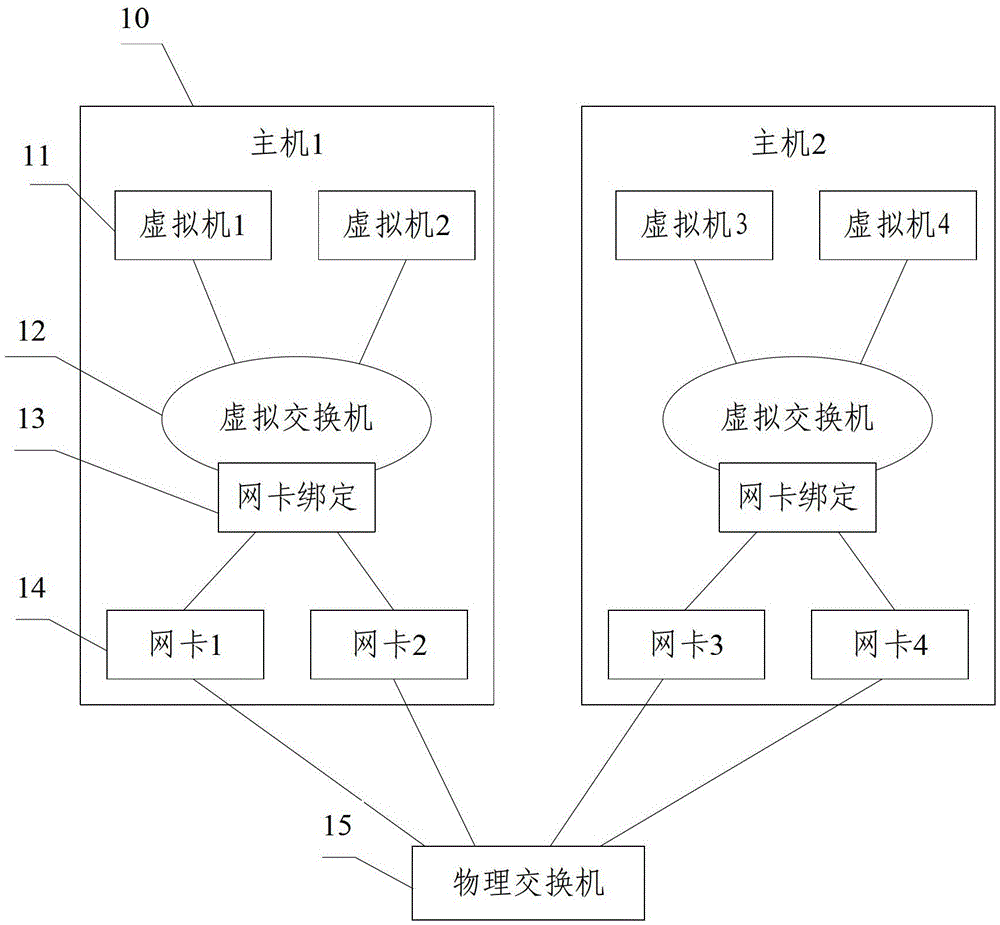
[0035] Embodiment 1 of the present invention provides a virtual network that realizes traffic isolation control, and the structural diagram is as follows figure 1 As shown, the overall structure of the virtual network is described, including:

[0036] A virtual machine 11 , a virtual switch 12 , a network card binding 13 , a physical network card 14 and a physical switch 15 .

[0037] The virtual switch 12 controls all the virtual machines 11 connected to it, the network card binding 13 binds multiple physical network cards 14 into one virtual network card, and the physical switch 15 controls the network traffic on the physical network cards 14 connected to it.

[0038] There are many ways to implement this virtual network, which can be realized by using Linux bonding (network card bonding technology) and Linux traffic control tool TC.

[0039] The virtual machine 11, the virtual switch 12, the network card binding 13, and the physical network card 14 are all located in the h...

Embodiment 2

[0045] In order to achieve the above purpose, Embodiment 2 of the present invention also provides a virtual network construction method for implementing traffic isolation control. The flow chart of the specific steps is as follows Figure 4 shown, including the following steps:

[0046] Step S1: Create a binding of multiple physical network cards in each server to obtain a virtual network card.

[0047] When a server joins a cluster (cluster) to provide resources for a virtual machine (VM, VirtualMachine), each physical server will join the network card bond (bond) regardless of the number of network cards, and the name of each server network card bond (bond) Be consistent for unified management. The operation of creating a network card bond (bond) can be performed in the startup script of the server. Every time the server is restarted, the network card bond (bond) needs to be removed and rebuilt, so that the network status can be detected during the network card bond (bond)...


PUM


Abstract

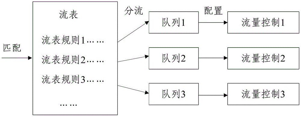
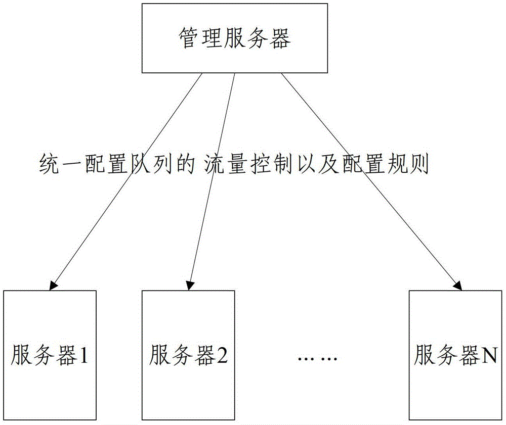
The invention discloses a virtual network and a construction method for realizing traffic isolation control. A virtual network is constructed through a virtual machine, a virtual switch, network card binding, a physical network card and a physical switch, and a management server controls all servers under the control of the management server. Configure physical network cards and virtual switches to control network traffic. The network provided by the present invention reduces the requirements for server network card configuration, the physical environment configuration is simple, and the network card binding technology is used to ensure high availability of the network. Even if some network cards are damaged, it will not affect the operation of various applications in the entire system, and the management is simple and can be dynamically based on demand. Do flow control.

Description

technical field [0001] The invention relates to the technical field of virtual network management, in particular to a virtual network and a construction method for realizing traffic isolation control. Background technique [0002] The virtual network is based on the switching technology, and the network nodes are divided into several "logical working groups" according to the nature and needs of the work. A "logical working group" is a virtual network. Many virtual machines can be virtualized on a host computer through a virtual machine, as long as the configuration of the real host is sufficient. Network management is an important part of the virtual machine network management platform. The main body of virtualization management: the virtual machine and the computing nodes and storage nodes that provide resources for the virtual machine all work in a network environment, and various software compete to occupy the network. Resources, if the isolation and shunt control is not...

Claims


Application Information

Patent Timeline
Patent Type & Authority Patents(China)
IPC IPC(8): H04L12/46H04L12/801
Inventor 王玥
Owner OPZOON TECH
Learn More