
Method for positioning mold line sample plate with positioning hole in repairing process

A die line template and positioning hole technology, which is applied to welding equipment, laser welding equipment, metal processing equipment, etc., can solve the problems of low production efficiency, waste of materials, scrap die line templates, etc.

Active Publication Date: 2013-06-12
SHENYANG AIRCRAFT CORP
View PDF5 Cites 4 Cited by
  • Summary
  • Abstract
  • Description
  • Claims
  • Application Information

AI Technical Summary

Problems solved by technology

[0002] At this stage, some sheet metal parts with positioning holes or pin holes and mold line template repair of machined parts are generally changed by workers manually. Insufficient accuracy, usually need to scrap the existing mold line template, and re-manufacturing process
If you encounter a large-scale mold line template with many lines and more complicated lines, it will not be easily scrapped when adding multiple viewports and adding lines. However, it is indeed a bit laborious to repair, and some areas are easy to repair. Deformation can result in inaccuracies in the rework area
The above situation will cause unnecessary waste of materials in actual production, which will cause deviations in the repair of the model, and the accuracy will decrease. At the same time, the production efficiency will also be low.

Method used


Image

  • Method for positioning mold line sample plate with positioning hole in repairing process

Examples


Embodiment Construction

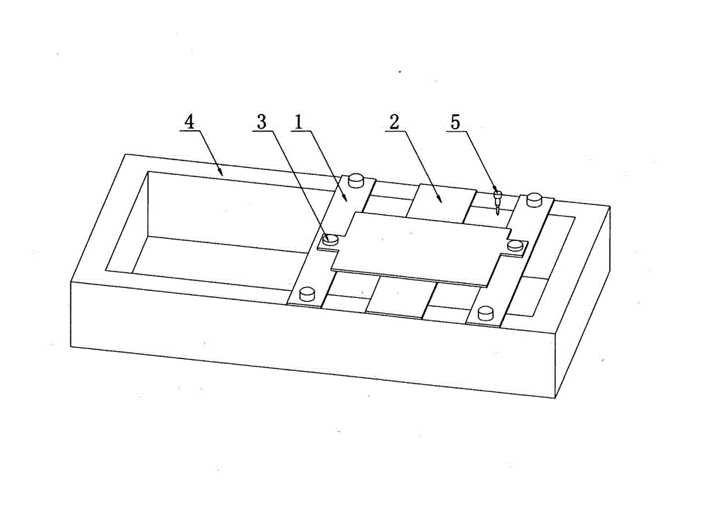
[0014] Such as figure 1 As shown, a method for positioning mold line templates with positioning holes in the repair process includes the following steps:

[0015] 1) Level the mold line template 2 and inspect it according to the polyester film to ensure that the positioning holes and outer edges of the mold line template are accurate;

[0016] 2) Compile the laser cutting program A with only the outer edge of the mold line template and the positioning hole, and ensure that the positioning hole is cut first, and then the outer edge is cut;

[0017] 3) Prepare the laser cutting program B that only has the outer edge of the mold line template and the repaired and modified parts, and ensure that the repaired and modified parts are cut first, and then the outer edge is cut;

[0018] 4) Increase the height of the laser head 5 of the laser cutting machine, and run the program A of the laser cutting machine. When the laser head is in the first positioning hole, press to stop the lase...


PUM


Abstract

The invention relates to a method for positioning a mold line sample plate with a positioning hole in a repairing process. The method comprises the steps that 1) the mold line sample plate is leveled; 2) a laser cutting program A is programmed; 3) a laser cutting program B is programmed; 4) the height of a laser head of a laser cutter is heightened, the laser cutter runs the laser cutting program A in an idling mode, when the laser head is positioned at a first positioning hole, the laser cutter is stopped, and a first positioning steel plate is put down and fixed; then the laser cutter runs in the idling mode continuously, when the laser head is positioned at a second positioning hole, the laser cutter is stopped, and a second positioning steel plate is put down and fixed; 5) the height of the laser head of the laser cutter is realigned; 6) and the laser cutter runs the laser cutting program B to machine the repaired part of the mold line sample plate. According to the method, the positioning holes in the mold line sample plate are utilized, the laser cutter can locate the accurate position of the mold line sample plate and carries out laser cutting on the repaired part, so that the machining accuracy is improved, and the working efficiency of sample plate repairing is also improved.

Description

technical field [0001] The invention relates to a positioning method for a mold line template with positioning holes in the repair process, which is used for the repair positioning of the mold line template. Background technique [0002] At this stage, some sheet metal parts with positioning holes or pin holes and mold line template repair of machined parts are generally changed by workers manually. Insufficient accuracy usually requires scrapping the existing mold line template and remanufacturing the process. If you encounter a large-scale mold line template with many lines and more complicated lines, it will not be easily scrapped when adding multiple viewports and adding lines. However, it is indeed a bit laborious to repair, and some areas are easy to repair. Deformation can result in inaccuracies in the rework area. The above situation will cause unnecessary waste of materials in actual production, which will cause deviations in the repair of the model, reduce the pr...

Claims


Application Information

Patent Timeline
IPC IPC(8): B23K26/38
Inventor 张云鹏
Owner SHENYANG AIRCRAFT CORP
Learn More