
Mold mechanism realizing inner core extraction by oblique ejectors and outer core extraction by outer sliding blocks

A technology of mold mechanism and slider, which is applied in the field of mold mechanism for drawing outer core by slider and inner core for inclined top, which can solve the problems of difficult to achieve mold clamping force, inconvenient manufacturing, installation, debugging, maintenance, and mold manufacturing cycle. Lengthening and other issues

Inactive Publication Date: 2013-06-12
牟维军
View PDF0 Cites 6 Cited by
  • Summary
  • Abstract
  • Description
  • Claims
  • Application Information

AI Technical Summary

Problems solved by technology

Although the above-mentioned mechanism works firmly and reliably, with good pressure transmission and good product quality, due to the limitation of the volume of the mold and the injection machine and die-casting machine, it is necessary to install hydraulic cylinders, pneumatic cylinders, rack and pinion, rifling lines, and inner slides on the mold. It is necessary to design corresponding auxiliary mechanisms to complete the installation of the above-mentioned parts, which increases the volume of the mold. At the same time, the design and manufacture of each auxiliary part wastes a lot of time, resulting in a longer mold manufacturing cycle.
In addition, due to the increase in mold volume, there are extremely high requirements on the pressure of injection machines and die-casting machines. Therefore, it is difficult to meet the required mold clamping force with ordinary die-casting machines or injection machines.
Therefore, only a special die-casting machine or a special injection machine is used for molding, which greatly increases the manufacturing cost.
At the same time, due to the installation of hydraulic cylinders, pneumatic cylinders, rifling lines, rack and pinions and other mechanisms on the mold, it brings difficulties such as manufacturing, installation, debugging, maintenance, and processing difficulties to the production line.

Method used


Image

  • Mold mechanism realizing inner core extraction by oblique ejectors and outer core extraction by outer sliding blocks
  • Mold mechanism realizing inner core extraction by oblique ejectors and outer core extraction by outer sliding blocks
  • Mold mechanism realizing inner core extraction by oblique ejectors and outer core extraction by outer sliding blocks

Examples


specific Embodiment approach

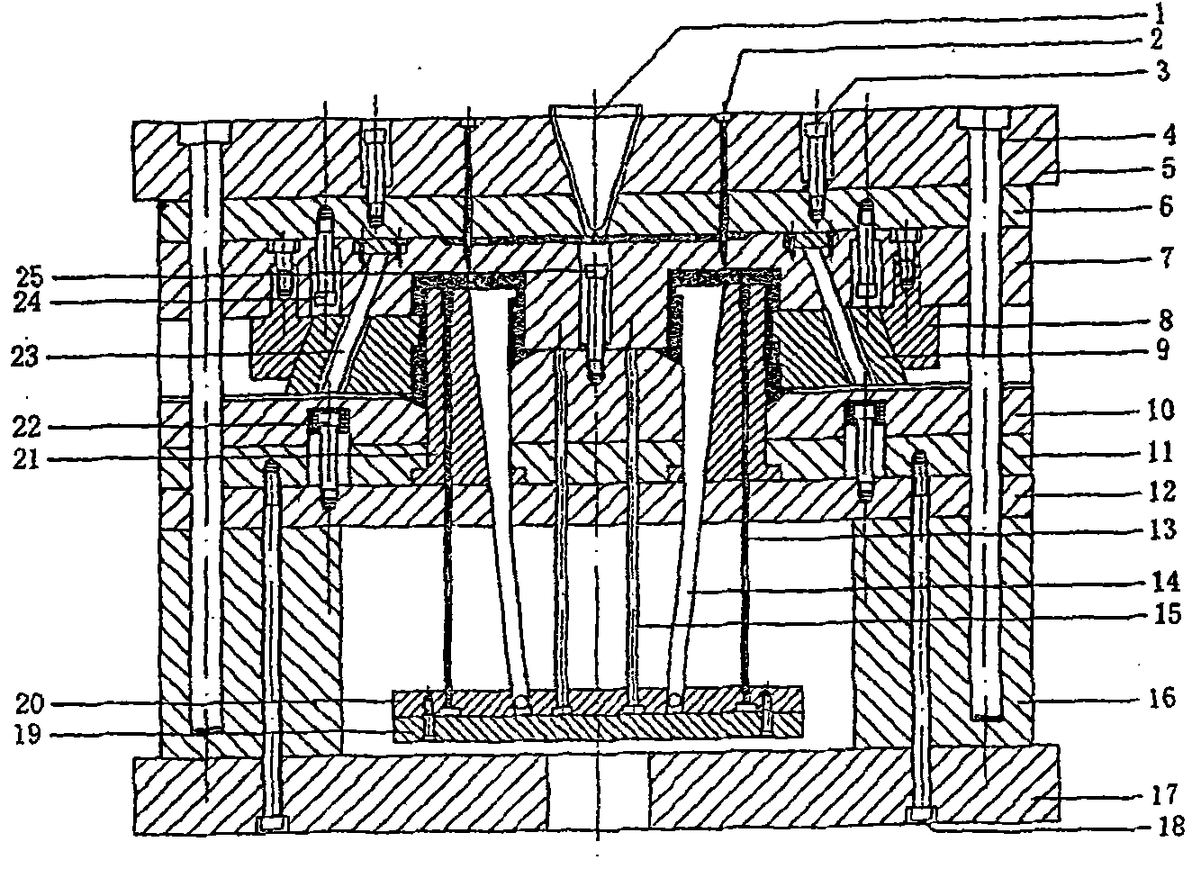
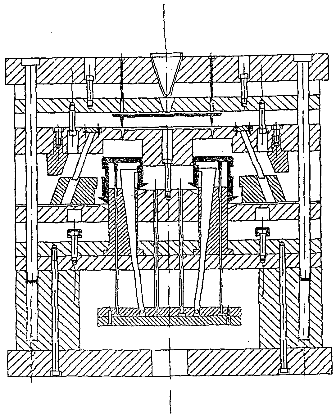
[0010] As shown in the figure, it is a mold mechanism in which the inclined top draws the inner core and the slider draws the outer core. Its specific implementation is as follows:

[0011] After the mold is injected or die-casted, the movable mold part of the mold moves with the injection machine or die-casting machine, and the product is pulled to the movable mold side by the core (21). At this time, the diagonal tie rod (23) installed on the fixed mold side forces the outer slider (9) In the T-shape of the movable template (10), make a sliding action in the direction of the outer side of the mold, and slide until there is a 3-4 mm gap between the molding part of the outer slider (9) and the product, and then the outer slider (9) stops moving. , so as to achieve the purpose of core pulling on the outer surface. The movable mold continues to move. When the mold opening distance is greater than the height of the product, the injection machine or die-casting machine stops. At ...


PUM


Abstract

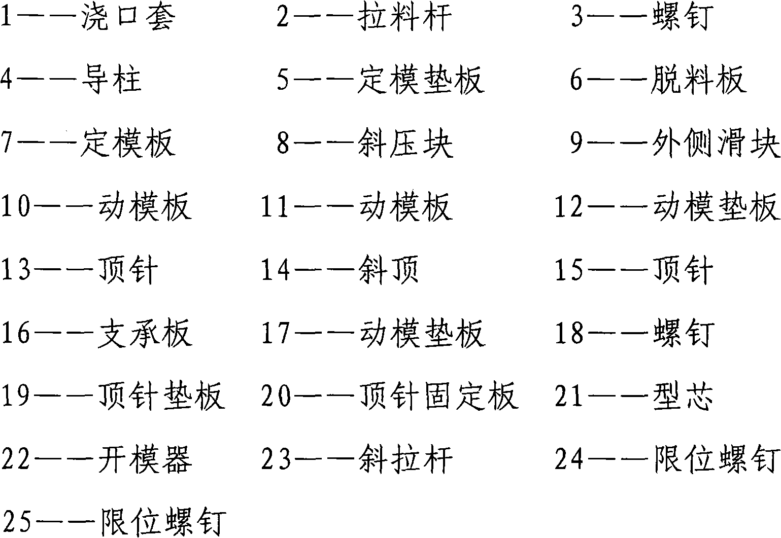
The invention discloses a mold mechanism realizing inner core extraction by oblique ejectors and outer core extraction by outer sliding blocks. The mold mechanism comprises a sprue bush, sprue pullers, bolts, a fixed mold base plate, a movable mold base plate, the outer sliding blocks, the oblique ejectors, ejector pins, a guide pillar, support plates, a fixed mold plate, a movable mold plate, a mold core and oblique press blocks. The outer sliding blocks installed on the outer side of the mold mechanism realize outer core extraction. The oblique ejectors installed in the mold mechanism carry out oblique sliding thereby finishing inner core extraction. The mold mechanism realizes firm and reliable operation, has good pressure transmission, is greatly simplified, is convenient for manufacture, installation, adjustment and maintenance, reduces a production cost, and is safe and environmentally friendly.

Description

technical field [0001] The invention relates to injection molding molds and metal die-casting molds, and is a mold mechanism in which an inclined top draws inner cores and a slider draws outer cores. Background technique [0002] At present, on plastic injection molds and metal die-casting molds, there are core-pulling mechanisms on the inner and outer sides of the product, which use hydraulic pressure, air pressure, rack and pinion, rifling lines, inner sliders, briquetting blocks and inclined guide columns to complete core-pulling. . Although the above-mentioned mechanism works firmly and reliably, with good pressure transmission and good product quality, due to the limitation of the volume of the mold and the injection machine and die-casting machine, it is necessary to install hydraulic cylinders, pneumatic cylinders, rack and pinion, rifling lines, and inner slides on the mold. The block, briquetting block and inclined guide post need to design corresponding auxiliary ...

Claims


Application Information

Patent Timeline
IPC IPC(8): B29C45/33B22D17/22
Inventor 牟维军
Owner 牟维军
Learn More