Mini-type gear drive mechanism of temperature-sensitive printer

A technology of gear transmission mechanism and thermal printer, which is applied in printing and other directions, can solve the problems of reduced gear train life, broken gear transmission mechanism, and high maintenance cost of the transmission mechanism, and achieves small size, affordable, and high-quality gear transmission mechanism. compact effect

Inactive Publication Date: 2013-06-12
YANGXIN PRINTING EQUIP SHANGHAI
View PDF12 Cites 0 Cited by
  • Summary
  • Abstract
  • Description
  • Claims
  • Application Information

AI Technical Summary

Problems solved by technology

The operation of untrained users will lead to a reduction in the life of the gear train of the transmission mechanism. Users tend to tear the receipts output by the printer forcefully, usually after a few months, the gear transmission mechanism will be broken, resulting in increased maintenance costs.

Method used


Image

  • Mini-type gear drive mechanism of temperature-sensitive printer
  • Mini-type gear drive mechanism of temperature-sensitive printer
  • Mini-type gear drive mechanism of temperature-sensitive printer

Examples


Embodiment Construction

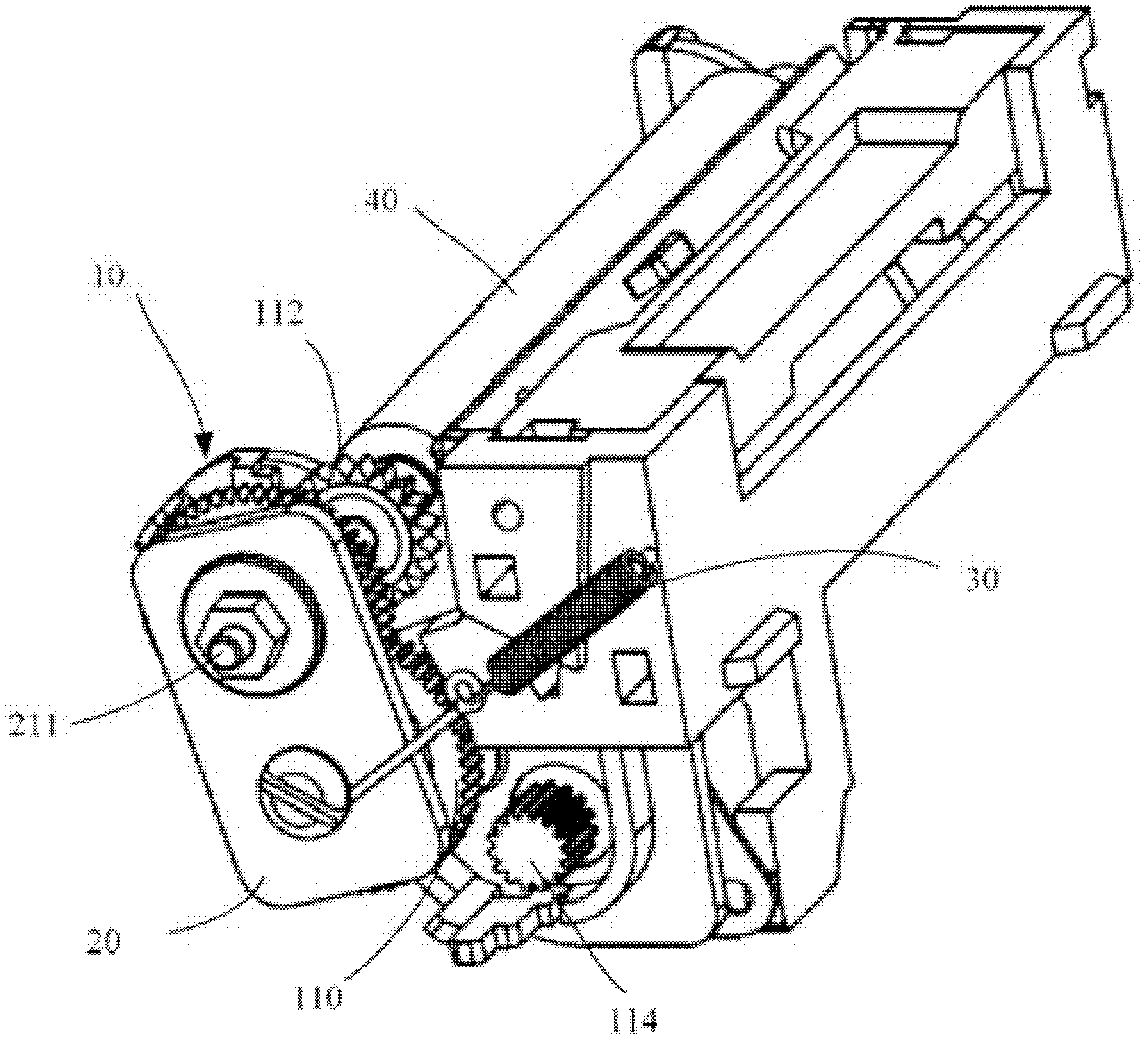
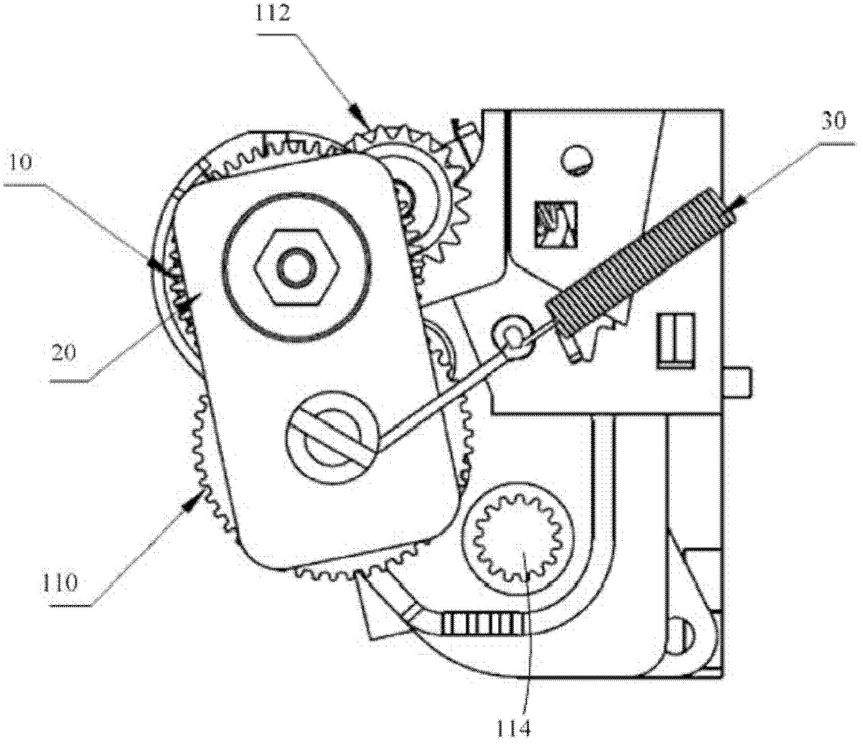
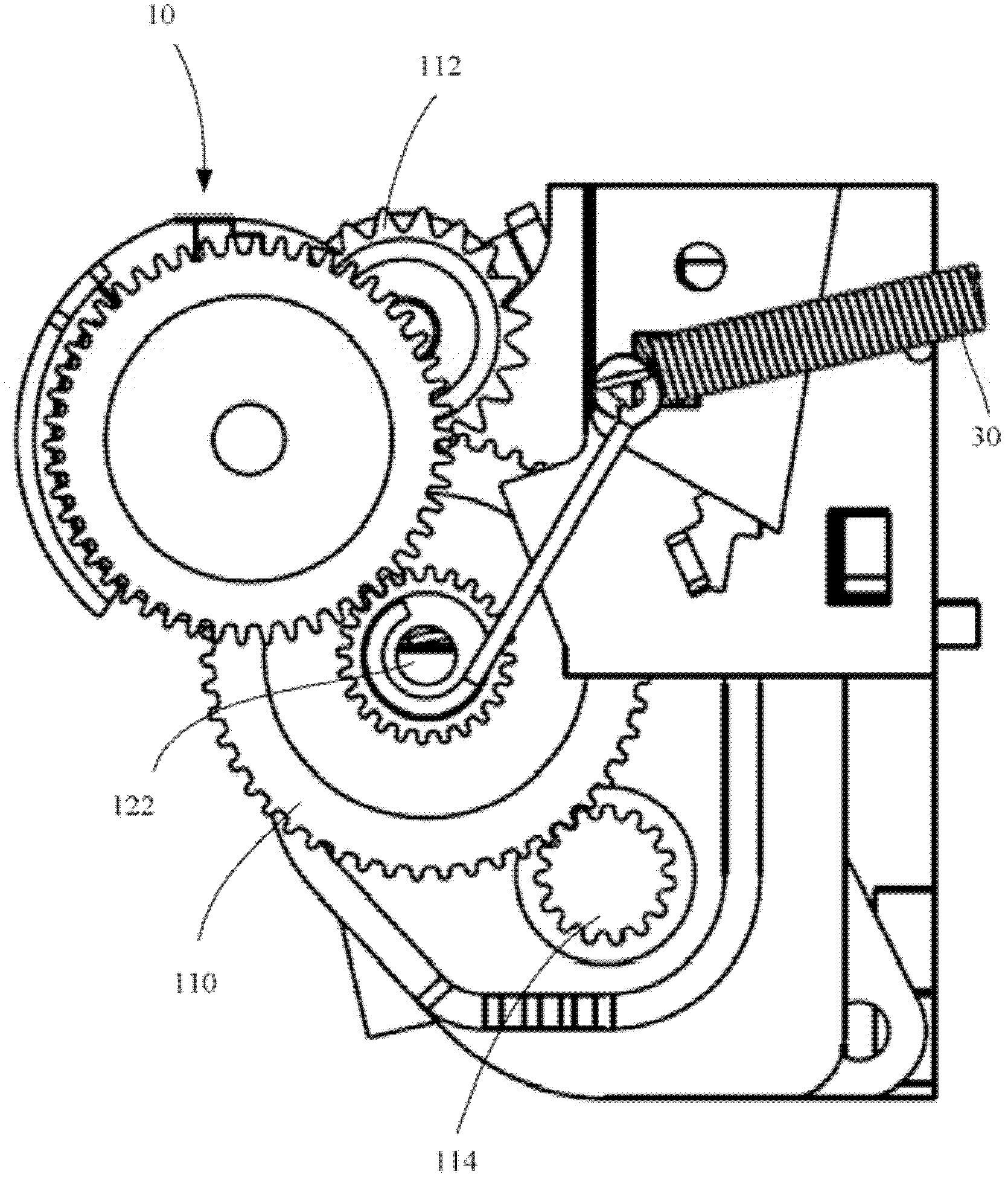
[0023] Such as figure 1 with figure 2 As shown, the gear transmission mechanism of the micro thermal printer includes a gear train 10, a movable plate 20 and a spring 30. The gear train 10 includes a plurality of fixed gears with fixed axes and a movable gear 110 with a movable axis. Among the multiple fixed gears, the motor gear 114 connected to the output shaft of the stepping motor is located at one end of the gear train, and the roller gear 112 coaxially connected to the rubber roller 40 is located at the other end of the gear train. Among the multiple fixed gears There are other gears, so I won’t repeat them here. In the gear train 10, the movable gear 110 is located between the roller gear 112 and the motor gear 114. Preferably, the movable gear 110 meshes adjacently with the motor gear 114, but is not limited to this. For example, the movable gear 110 may be engaged with a roller. The gears 112 are meshed adjacently, or there are other gears spaced apart.

[0024] Such a...


PUM


Abstract

The invention aims at providing a gear drive mechanism of a temperature-sensitive printer. The gear drive mechanism of the temperature-sensitive printer can be suitable for a user habit of forcibly tearing notes and has long service life. The gear drive mechanism of the temperature-sensitive printer comprises a gear train which comprises a motor gear and a roller gear, wherein the motor gear is connected on a power output shaft of a stepping motor and the roller gear is located on a rubber roller. The gear drive mechanism of the temperature-sensitive printer is characterized in that the gear train further comprises a movable gear, the movable gear is located at any position between the motor gear and the roller gear of the gear train, the movable gear is supported by a movable part so that the movable gear can move and the gear train can be disconnected at the position of the movable gear.

Description

Technical field [0001] The invention relates to a thermal printer. Background technique [0002] A thermal printer generally includes a fixed thermal print head, a motor, a rubber roller, a mechanical transmission mechanism, one or more springs, and a frame supporting the aforementioned components. The thermal print head is composed of a plurality of thermal dots forming a thermal line, and these thermal dots can be selectively activated to generate enough heat to blacken the pretreated thermal paper. The motor is generally a stepping motor, which moves the paper sequentially, and activates and combines with the thermal end to form a bitmap on the paper. The rubber roller keeps the paper in soft and continuous contact with the thermal head. A mechanical transmission mechanism transmits power from a stepper motor to a rubber roller, and usually includes a gear train. The spring presses the thermal head against the rubber roller. [0003] The development and progress of technolog...

Claims


Application Information

Patent Timeline
Patent Type & Authority Applications(China)
IPC IPC(8): B41J23/02
Inventor 德尼·蒙塔居泰利
Owner YANGXIN PRINTING EQUIP SHANGHAI
Why Eureka
Try Eureka