Ordinary gear train and non-uniform transmission mechanism combined power transmission device

A technology of transmission mechanism and fixed axle gear train, applied in the direction of gear transmission, differential transmission, transmission, etc., can solve the problems of difficult processing, low power density, difficult to balance the whole machine, and achieve the stability of the whole machine Improves, prolongs service life, and facilitates balanced effects

Inactive Publication Date: 2013-10-02
NAT UNIV OF DEFENSE TECH
View PDF6 Cites 0 Cited by
  • Summary
  • Abstract
  • Description
  • Claims
  • Application Information

AI Technical Summary

Problems solved by technology

Although these studies have improved the power performance of the reciprocating piston engine to a certain extent, they have not fundamentally changed the current situation of low power density of the engine due to the inherent defects of the power transmission part.
The successful development and application of the rotary piston engine is the triangular rotor rotary piston engine invented by German Wankel in 1957. This engine has relatively high power density and promising application prospects, but the manufacturing cost is high due to the complicated shape of the rotor. , and there are difficult problems such as difficult sealing, poor power performance at low speed, poor fuel economy, etc., so that the theoretical superiority of the rotary piston engine has not been fully utilized so far.
[0004] The lower power density not only restricts the further improvement of the performance of the piston engine, but also limits the application of the piston engine in many occasions
The above two types of piston engines are limited by the inherent defects of the power transmission part, and the power density is difficult to reach 1 (Kw / Kg)
The low power density of power sources has become a bottleneck in the development of some equipment technologies
[0005] In order to improve the characteristics of traditional piston engines, various solutions have been proposed, among which the dual-rotor piston engine is a very popular research direction. Over the years, a large number of researches have been carried out at home and abroad. breakthroughs have been made, but there are two problems in the existing double-rotor piston engine research that are difficult to solve
[0006] First, the differential drive assembly that constrains the motion of the rotor is complex
In the literature that has been found, some people use difficult-to-machine parts such as oval gears, transmission gears, non-circular gears, and oval gears to realize differential drive rotors. These solutions are not only high in cost, but also poor in reliability, especially for When the high power density of the engine is required to perform more work per revolution of the power shaft, the shape of these special parts will become very complicated and the processing will be too difficult; others use unconventional parts such as one-way devices, ratchets, and springs. To achieve differential drive rotors, as we all know, these components do not have practical value when used as parts for engine power transmission, and there will be great impact when the rotor rotates at a non-uniform speed, and the running noise is very loud; some people also use gears, Conventional components such as connecting rods realize differential drive rotors, but the mechanism scheme is either too complicated to implement, or the number of planetary gears is large, making it difficult to balance the whole machine
Secondly, it is difficult to achieve more than 10 times of work per revolution of the power shaft, which cannot guarantee the high power density of the engine

Method used


Image

  • Ordinary gear train and non-uniform transmission mechanism combined power transmission device
  • Ordinary gear train and non-uniform transmission mechanism combined power transmission device
  • Ordinary gear train and non-uniform transmission mechanism combined power transmission device

Examples


Embodiment Construction

[0034] The present invention will be further described in detail below in conjunction with the accompanying drawings and specific embodiments.

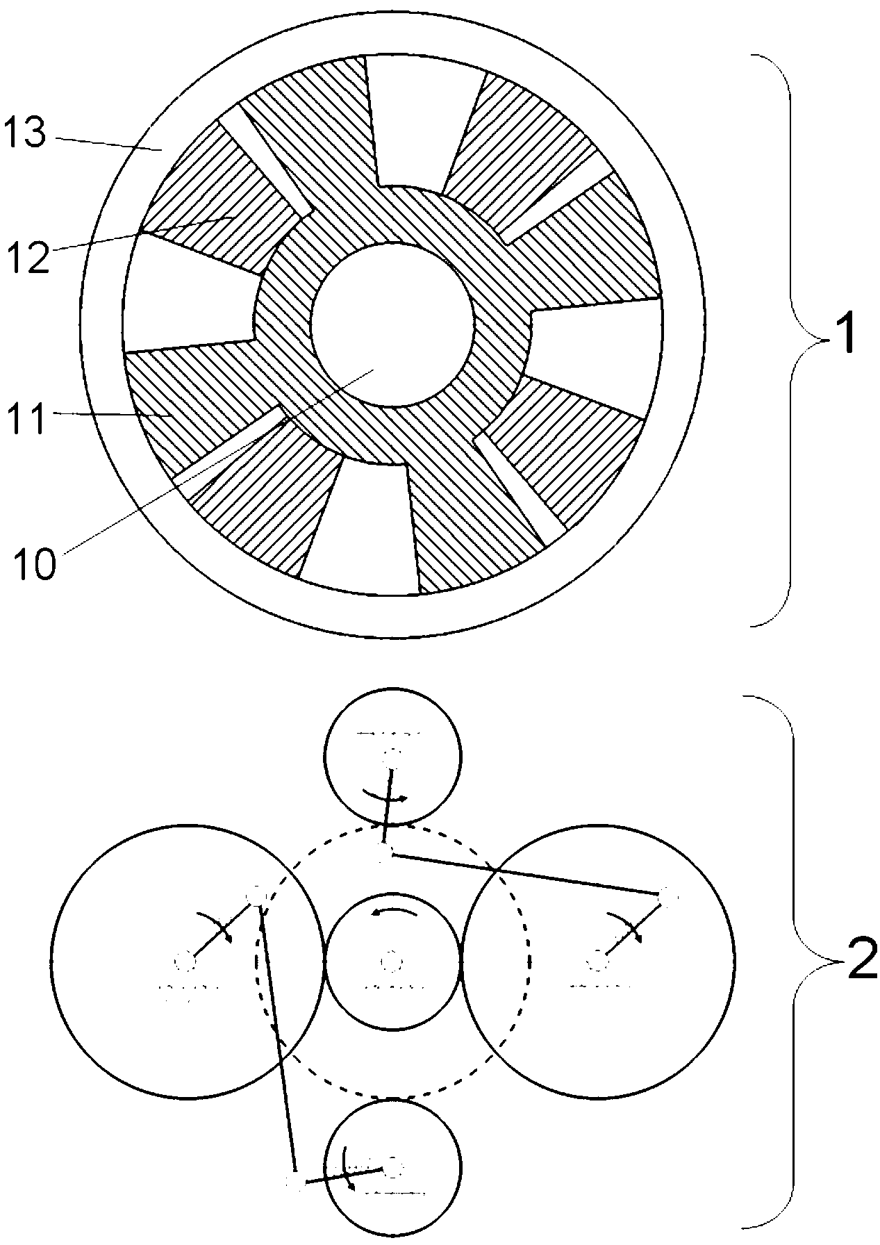
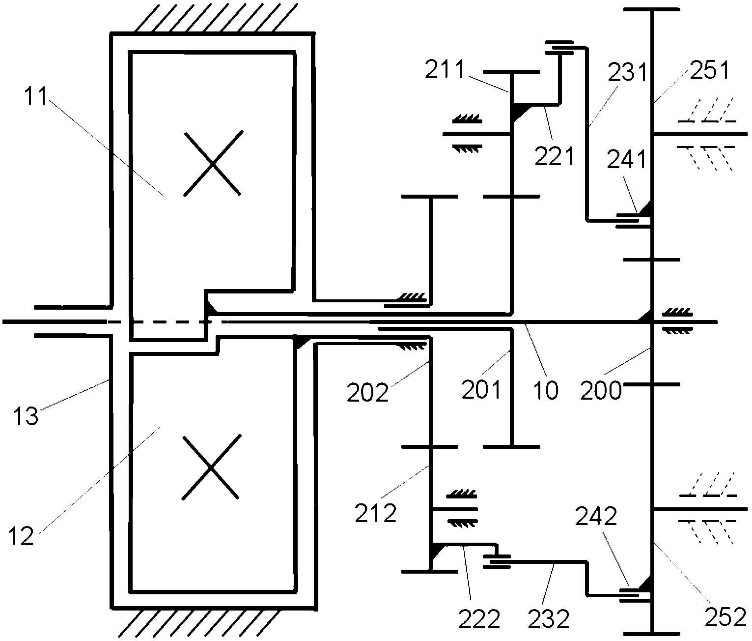
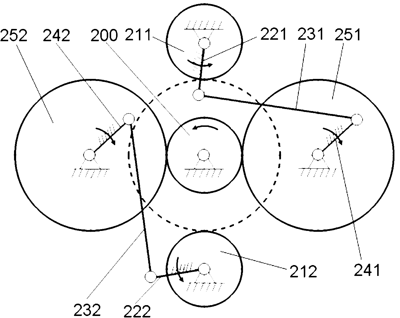
[0035] Such as figure 1 , figure 2 , image 3As shown, in the first embodiment, the power transmission device of the present invention combining a fixed-axis gear train and a non-uniform speed transmission mechanism includes a power cylinder assembly 1, a power shaft 10, and a differential drive assembly 2 connected to the power cylinder assembly 1, The power cylinder assembly 1 includes a rotor I11, a rotor II12 and a cylinder body 13. The rotor I11 and the rotor II12 are coaxially installed in the cylinder body 13 in a cross shape and can rotate around the axis of the power shaft 10. The differential drive assembly 2 includes a set of fixed-axis gear trains and two sets of non-uniform speed transmission mechanisms. The fixed-axis gear train and non-uniform speed transmission mechanisms are combined to form a drive assembly with a...


PUM


Abstract

The invention discloses an ordinary gear train and non-uniform transmission mechanism combined power transmission device. The device comprises a power cylinder assembly and a differential drive assembly connected with the power cylinder assembly, wherein the power cylinder assembly comprises a rotor I, a rotor II, a power shaft and a cylinder body; the rotor I and the rotor II are coaxial, crosswise arranged in the cylinder and rotate around the axes of the power shaft; the differential drive assembly is a drive assembly which is formed by combination of a set of ordinary gear train and two sets of non-uniform transmission mechanisms, and has the degree of freedom to be 1; and the drive assembly is provided with two input ends and an output end, the two input ends of the drive assembly are connected with the rotor I and the rotor II respectively, and the output end of the drive assembly is connected with the power shaft. The ordinary gear train and non-uniform transmission mechanism combined power transmission device has the advantages: the structure is simple, the transmission is stable, the whole machine is easily balanced, the power shaft does more work when rotating for a circle and the like.

Description

technical field [0001] The invention mainly relates to the field of volumetric machines, in particular to a power transmission device applicable to high power density double-rotor piston engines. Background technique [0002] Positive displacement machines include mechanical equipment such as piston engines, compressors, pumps, etc. The present invention specifically relates to the improvement of the power transmission part of the engine, and the related method and structure are also suitable for the improvement of air motors, compressors, pumps and other equipment with slight modifications. [0003] Piston engines mainly include reciprocating piston engines and rotary piston engines. A crank linkage is used for power transmission on most reciprocating piston engines. For more than 100 years, researchers have carried out extensive research on the crank connecting rod mechanism, and at the same time, they are committed to reducing the inertial load and side pressure, overco...

Claims


Application Information

Patent Timeline
Patent Type & Authority Patents(China)
IPC IPC(8): F16H37/00F16H1/22F16H48/12F16H21/12F02B53/02
CPCY02T10/17Y02T10/12
Inventor 徐海军潘存云邓豪陈虎张威扬邹腾安
Owner NAT UNIV OF DEFENSE TECH
Why Eureka
Try Eureka