Polar roaming spherical robot
A spherical robot, robot technology, applied in the direction of extraterrestrial vehicles, etc., can solve the problems of internal system power supply needs, insufficient sunlight, single movement direction, etc., to achieve the effect of energy utilization and all-round movement
- Summary
- Abstract
- Description
- Claims
- Application Information
AI Technical Summary
Problems solved by technology
Method used
Image
Examples
Embodiment 1
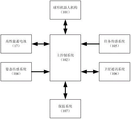
[0026] Embodiment one: if figure 1 As shown, the polar roaming spherical robot includes a spherical robot mechanism (101), a main control system (102), a high-performance battery (17), an attitude sensing system (104), a mission sensing system (105), a satellite positioning communication system (106) and heat preservation system (107), characterized in that the main control system (102), high-performance battery (103), attitude sensing system (104), The task sensing system (105) and the satellite positioning communication system (106), the main control system (102) is connected with the high-performance battery (17) to complete the system power supply and wind-driven power generation management functions; the main control system (102) It is connected with the attitude sensor (104) to obtain the current attitude information of the robot; the main control system (102) is connected to the task sensing system (105) to obtain the temperature and humidity information of the current ...
Embodiment 2
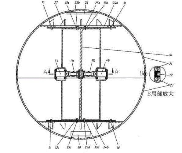
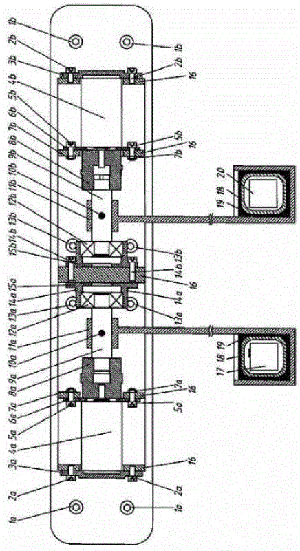
[0028]Embodiment 2: This embodiment is basically the same as Embodiment 1, and the special feature is: see figure 2 , the spherical robot mechanism (101) adopts a symmetrical spherical structure to complete the functions of robot support and body cover protection, and install and fix various systems (102, 103, 104, 105, and 106) inside. The mechanism includes screws (1a, 1b , 1c, 1d, 2a, 2b, 5a, 5b, 10a, 10b, 13a, 13b, 13c, 13d, 14, 22), two left and right motor fixing plates (3a, 3b), two left and right brushless DC motors ( 4a, 4b), two left and right motor auxiliary mounting plates (6a, 6b), nuts (7a, 7b, 25a, 25b, 25c, 25d), left and right couplings (8a, 8b), left and right shafts (9a, 9b) , left and right counterweight brackets (11a, 11b), left and right bearings (12a, 12b), left and right bearing seats (15a, 15b), inner frame support frame (16), high-performance battery (17), resistance film (18), insulation Filling material (19), electronic system (20), upper and lowe...
Embodiment 3
[0030] Embodiment 3: This embodiment is basically the same as Embodiment 2, and the special feature is: see image 3 , the structure of the main control system (102): a microprocessor (301) is respectively connected to the left and right drive inverter bridge circuits (302a, 302b) via the left and right drive isolation circuits (303a, 303b), and connected to the left and right two A current detection circuit (304a, 304b), connected to two left and right brushless DC motors (4a, 4b) via two left and right position sensing circuits (305a, 305b), connected to a power state detection circuit (306), and a heat preservation control system ( 107), a reset circuit (307) and an interface conversion circuit (308), the left and right two detection circuits (304a, 304b) and the left and right brushless DC motors (4a, 4b) are respectively connected to the left and right drive inverter bridges circuits (302a, 302b), the interface conversion circuit (308) is connected to the attitude sensing...
PUM
 Abstract
Description
Claims
Application Information
 - R&D
- Intellectual Property
- Life Sciences
- Materials
- Tech Scout
- Unparalleled Data Quality
- Higher Quality Content
- 60% Fewer Hallucinations
Browse by: Latest US Patents, China's latest patents, Technical Efficacy Thesaurus, Application Domain, Technology Topic, Popular Technical Reports.
© 2025 PatSnap. All rights reserved.Legal|Privacy policy|Modern Slavery Act Transparency Statement|Sitemap|About US| Contact US: help@patsnap.com


