Bridge used for direct current insulation monitoring device and running method thereof

A monitoring device and DC insulation technology, applied in the direction of AC/DC measuring bridge, etc., can solve the problems affecting operation and maintenance personnel, low fluctuating voltage, large fluctuation of busbar-to-ground voltage, etc., and achieve accurate measurement

Active Publication Date: 2013-06-12
BEIJING PEOPLES ELECTRIC PLANT
View PDF6 Cites 14 Cited by
  • Summary
  • Abstract
  • Description
  • Claims
  • Application Information

AI Technical Summary

Problems solved by technology

[0019] However, due to the low fluctuating voltage, the calculation accuracy of insulation resistance will be greatly reduced, which will affect the performance of monitoring action, and then affect the correct fault judgment of operation and maintenance personnel.
[0020] In the prior art, a detection bridge with a fixed resistance value is used to detect the insulation resistance of the DC system. If the ratio between the resistance value of

Method used


Image

  • Bridge used for direct current insulation monitoring device and running method thereof
  • Bridge used for direct current insulation monitoring device and running method thereof
  • Bridge used for direct current insulation monitoring device and running method thereof

Examples


Embodiment 1

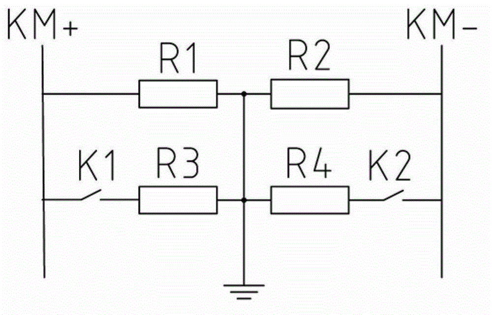
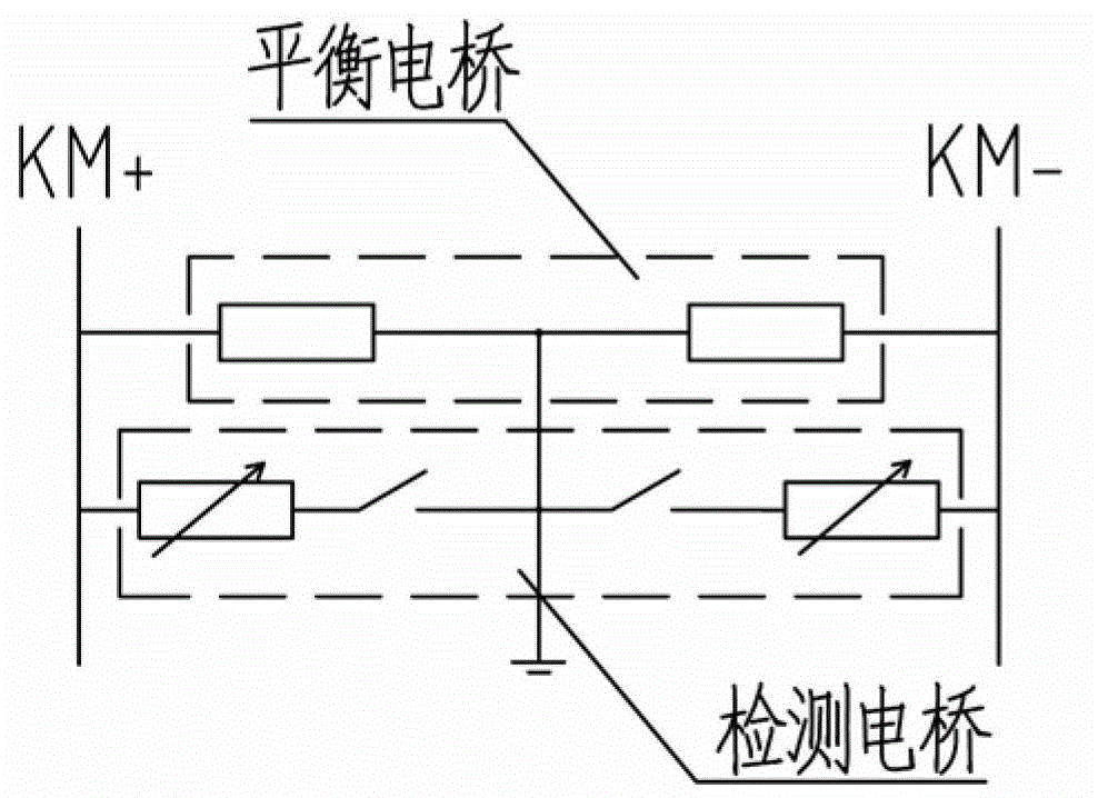
[0044] Such as image 3 As shown, it is the first embodiment of the electric bridge used in the DC insulation monitoring device of the present invention. The resistor R1 is connected between the positive pole KM+ of the DC bus and the ground, and the resistor R2 is connected between the negative pole KM- of the branch bus and the ground. Generally, In terms of resistor R1 and resistor R2, the resistance values ​​are equal to form a balanced bridge; after resistor R3 is connected in series with switch K1, it is connected between the positive electrode KM+ of the DC bus and the ground; after resistor R4 is connected in series with switch K2, it is connected to the DC Between the negative electrode KM- of the busbar and the ground, the resistor R3, the resistor R4, the switch K1, and the switch K2 together form a detection bridge, wherein at least one of the resistor R3 and the resistor R4 is variable and controllable.

Embodiment 2

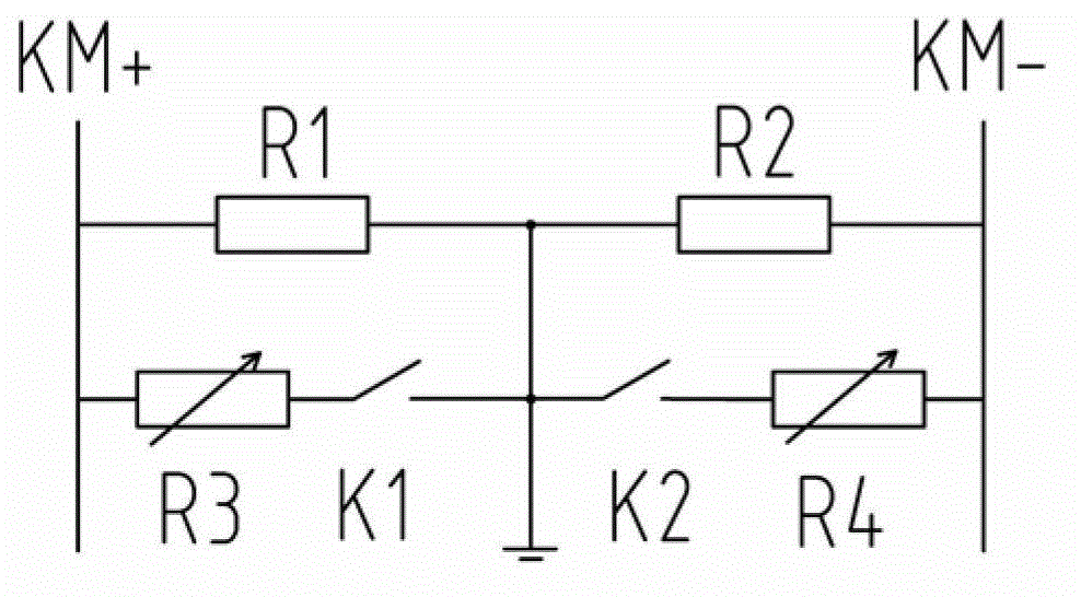
[0046] Such as Figure 4As shown, it is the second embodiment of the electric bridge used in the DC insulation monitoring device of the present invention. The resistor R1 is connected between the positive pole KM+ of the DC busbar and the ground, and the resistor R2 is connected between the negative pole KM- of the branch busbar and the ground. Generally, In terms of resistance R1 and resistor R2 are equal in resistance and form a balanced bridge together; after resistor R3 and switch K1 are connected in series, they are connected between the positive pole KM+ of the DC bus and the ground, and resistor R3 and switch K1 together form a detection bridge. , Resistor R3 is variable and controllable. Different from Embodiment 1, the detection bridge of this embodiment is only applied between the positive pole of the DC bus and the ground.

Embodiment 3

[0048] Such as Figure 5 As shown, it is the third embodiment of the electric bridge used in the DC insulation monitoring device of the present invention. The resistor R1 is connected between the positive pole KM+ of the DC busbar and the ground, and the resistor R2 is connected between the negative pole KM- of the branch busbar and the ground. Generally, In terms of resistor R1 and resistor R2, the resistance values ​​are equal to form a balanced bridge; resistor R3 and switch K1 are connected in series and connected between the DC bus negative pole KM- and the ground, and resistor R3 and switch K1 together form a detection bridge. Wherein, the resistor R3 is variable and controllable. Different from implementation example 1 and implementation example 2, the detection bridge of this implementation example is only applied between the negative pole of the DC bus and the ground.

[0049] In the above three embodiments, there are two implementations of the variable resistor R3 o...


PUM


Abstract

The invention provides a bridge used for a direct current insulation monitoring device and a running method of the bridge used for the direct current insulation monitoring device. The bridge comprises a balanced bridge and a detection bridge, wherein the balanced bridge is composed of a balanced resistor R1 and a balanced resistor R2, wherein the balanced resistor R1 is connected between a bus positive pole and the earth, and the balanced resistor R2 is connected between a bus negative pole and the earth. The detection bridge is composed of a detection resistor R3, a detection resistor selector switch K1 and/or a detection resistor R4 and a detection selector switch K2, wherein the detection resistor R3 and the detection resistor selector switch K1 are connected between the bus positive pole and the earth, and the detection resistor R4 and the detection resistor selector switch K2 are connected between the bus negative pole and the earth. For the detection resistor R3 connected between the bus positive pole and the earth and the detection resistor R4 connected between the bus negative pole and the earth, at least one of the R3 and the R4 is changeable and controllable. The bridge used for the direct current insulation monitoring device has the advantages of carrying out insulation monitoring by utilization of the detection bridge with the changeable resistor, being capable of changing the resistance value of the detection bridge in a self-adaptation mode according to direct earth capacitance and insulation resistance of a direct current system and taking safety of the direct current system and accuracy of insulation resistance measuring into account.

Description

technical field [0001] The invention belongs to the field of DC IT system insulation monitoring, and in particular relates to an electric bridge used for DC insulation monitoring and an operating method thereof. Background technique [0002] The DC insulation monitoring device used in substations or power plants generally performs insulation monitoring by combining the balance bridge and the detection bridge. Negative pole-to-ground voltage value, use the measured positive and negative pole-to-ground voltage values ​​to calculate the positive pole-to-ground insulation resistance and negative pole-to-ground insulation resistance of the DC system. [0003] figure 1 It is the principle of DC insulation monitoring technology commonly used at present. Among them, resistor R1 and resistor R2 form a balanced bridge, and their resistance values ​​are equal. Switching element K1, switching element K2, resistor R3 and resistor R4 together form a detection bridge. Generally speaking ...

Claims


Application Information

Patent Timeline
IPC IPC(8): G01R17/10
Inventor 王雪楠南寅李明波姜龙
Owner BEIJING PEOPLES ELECTRIC PLANT
Why Eureka
Try Eureka