Control circuit of time relay

A time relay and control circuit technology, applied in relays, electrical program control, circuits, etc., can solve problems such as false triggering of time relays, inconvenient connection between external trigger devices and time relays, false triggering of leakage currents, etc., and achieve reliable work. Effect

Active Publication Date: 2013-06-12
ZHEJIANG CHINT ELECTRIC CO LTD
View PDF4 Cites 23 Cited by
  • Summary
  • Abstract
  • Description
  • Claims
  • Application Information

AI Technical Summary

Problems solved by technology

At present, in order to expand the use function of the time relay, people try to selectively add a trigger signal input terminal for parallel connection with the external trigger device in the trigger signal processing circuit, and the external trigger device often has leakage current, that is, there is no leakage current in the external trigger device. In the state of trigger signal output, there is still weak current output to the output circuit and timing / delay circuit of the time relay, but the control circuit of the existing time relay does not allow the trigger signal processing circuit to have leakage current or large leakage current (such as 100mA level), because if there is a leakage current, it will cause false triggering of the time relay, that is, in the state where the trigger signal processing circuit has no trigger signal output, the leakage current will also trigger the output circuit of the time relay and the timing / delay The working state of the time circuit changes; the second is that the connection between the external trigger device and the time relay is inconvenient and unsafe, because one end of the control circuit of the trigger device must be fixedly connected to the L pole (or N pole) of the AC power supply. Specifically: for the time relay that allows the trigger device to be connected to the L pole of the AC power supply, the trigger device is not allowed to be connected to the N pole of the AC power supply; for the time relay that allows the trigger device to be connected to the N pole of the AC power supply, it is not allowed Allow the trigger device to be connected to the L pole of the AC power supply
[0004] Therefore, in order to avoid the defect of false triggering of leakage current, the control circuit of the existing time relay does not allow a weak conduction element or an external trigger device to be connected in parallel with the trigger switch, and the normally open contact of the matching trigger switch is not allowed There are other components that can generate a certain current in parallel between them, or it is not allowed to connect an external trigger device that is not dedicated to the time relay of this product model, thus limiting the function of the time relay, the expansion of use and the improvement of the safety level.

Method used


Image

  • Control circuit of time relay
  • Control circuit of time relay

Examples


Embodiment Construction

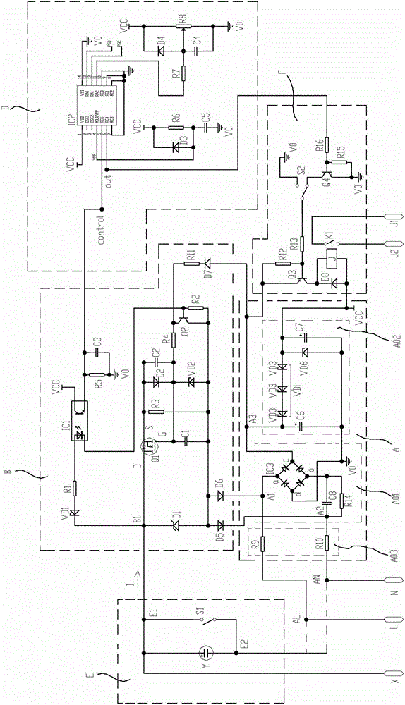
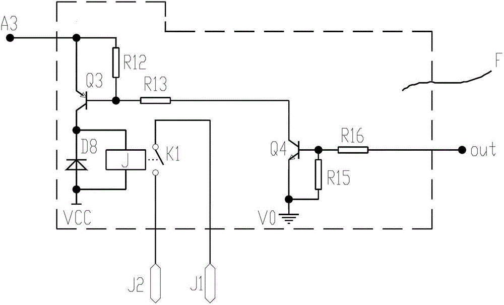
[0021] The following is attached figure 1 and figure 2 The given examples describe in detail the specific implementation of the control circuit of the time relay of the present invention. figure 1 , 2 Respectively are the circuit schematic diagrams of two implementations of the relay output circuit F of the control circuit of the time relay of the present invention, wherein figure 1 The relay output circuit F in has a selector switch S2, while figure 2 The relay output circuit F in has no selector switch S2. The control circuit of the time relay of the present invention is not limited to the description of these specific embodiments.

[0022] see figure 1 , the control circuit of the time relay of the present invention includes a timing / delay circuit D, a relay output circuit F, a step-down rectification and voltage stabilization circuit A, a trigger signal processing circuit B and a leakage trigger circuit E, and also includes functions that all time relays have The f...


PUM


Abstract

The invention discloses a control circuit of a time relay. A timing / delay circuit comprises a trigger control signal input node control and a control output node out connected with the control input end of a relay output circuit, and further comprises an electric-leakage trigger circuit with a trigger switch, and a trigger signal processing circuit, wherein a normally-open trigger contact of the trigger switch is optionally connected with a weak switch-on element and an outer trigger terminal in parallel, the trigger switch, the weak switch-on element and the outer trigger terminal are connected mutually to form a node which is connected with an input node of the trigger signal processing circuit, and the trigger switch is connected with the other end of the weak switch-on element to form a node which can be directly connected to any one of a pole L or a pole N on the alternating-current input side of a step-down rectifying voltage stabilizing circuit. The electric-leakage trigger circuit provides a control signal to the trigger signal processing circuit and afterwards triggers the timing / delay circuit, thus controlling the relay output circuit to realize the on / off state switching of a load, and when a current generated by a parallel element loop does not exceed a predetermined current threshold, the time relay is not triggered. The control circuit of the time relay provided by the invention is simple and allows weak current to flow through a normally-open contact serving as the trigger device without leading to false trigger.

Description

technical field [0001] The invention relates to a control circuit of a time relay, in particular to a control circuit of a time relay which allows the use of a switch with a weak conduction element connected in parallel between disconnected contacts as a trigger device. Background technique [0002] The time relay is widely used in various fields as a control device. The time relay includes a control circuit for controlling the on / off of its output circuit. The control circuit includes a power supply circuit, a trigger signal processing circuit, a timing / delay circuit and an electromagnetic relay output circuit. . The power supply circuit is used to supply power to the control circuit, the trigger signal processing circuit is used to control the on / off state transition of the output loop of the output circuit, and the timing / delay circuit is used to control the timing of the on / off state transition of the output loop of the output circuit and / or delay. The output terminals...

Claims


Application Information

Patent Timeline
Patent Type & Authority Applications(China)
IPC IPC(8): G05B19/04
CPCH01H47/002H01H47/18H02H3/093H03K17/28H03K17/7955H03K2017/515
Inventor 于雪峰苏敏郑光枢
Owner ZHEJIANG CHINT ELECTRIC CO LTD
Why Eureka
Try Eureka