Littrow-structure tunable external-cavity laser and mode-hopping-free sweep-frequency regulation method thereof

A laser and cavity-type technology, which is applied in the direction of the device for controlling the output parameters of the laser, the structure of the optical resonator, etc., can solve the problems that the large-scale non-mode-hopping tuning cannot be achieved, and achieve the effect of large-scale non-mode-hopping tuning

Active Publication Date: 2013-06-12
HARBIN INST OF TECH
View PDF2 Cites 12 Cited by
  • Summary
  • Abstract
  • Description
  • Claims
  • Application Information

AI Technical Summary

Problems solved by technology

[0012] The present invention is to solve the problem that the existing Littrow structure external cavity laser cannot realize large-scale non-

Method used


Image

  • Littrow-structure tunable external-cavity laser and mode-hopping-free sweep-frequency regulation method thereof
  • Littrow-structure tunable external-cavity laser and mode-hopping-free sweep-frequency regulation method thereof
  • Littrow-structure tunable external-cavity laser and mode-hopping-free sweep-frequency regulation method thereof

Examples


specific Embodiment approach 1

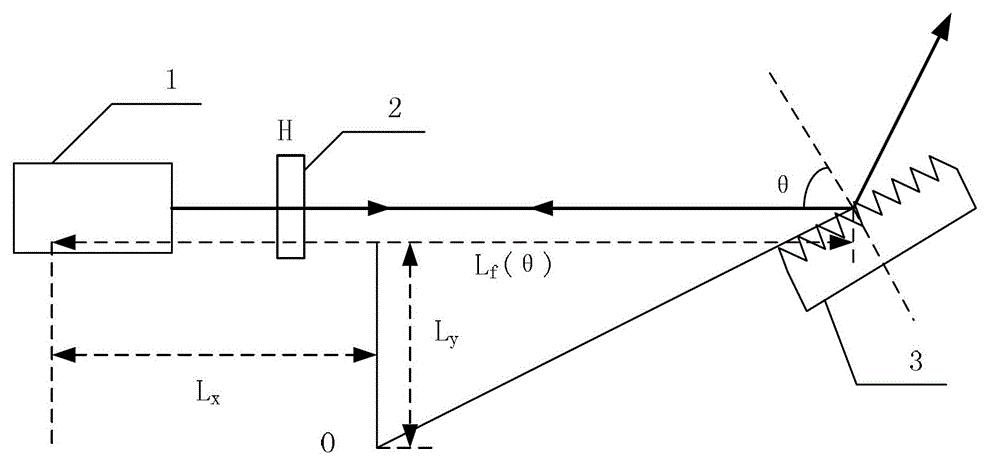
[0024] Specific implementation mode 1: the following combination figure 1 To explain this embodiment, the Littrow structure tunable external cavity laser described in this embodiment includes a semiconductor laser 1, and it also includes a liquid crystal spatial light modulator 2 and a blazed grating 3.

[0025] The laser beam emitted by the semiconductor laser 1 passes through the liquid crystal spatial light modulator 2 and enters the blazed grating 3, and the semiconductor laser 1 and the liquid crystal spatial light modulator 2 are sequentially arranged on the optical axis of the first-order diffraction of the blazed grating 3.

specific Embodiment approach 2

[0026] Specific implementation manner 2: the following combination figure 1 To describe this embodiment, this embodiment is based on the Littrow structure tunable external cavity laser described in the first embodiment.

[0027] The laser beam emitted by the semiconductor laser 1 is incident on the blazed grating 3 after passing through the liquid crystal spatial light modulator 2, and the first-order diffracted light returning from the original path after passing through the blazed grating 3 is in the inner cavity and outside of the tunable external cavity laser. Resonance is formed between the cavities, and finally emitted by the zero order of the blazed grating 3;

[0028] Rotate the blazed grating 3 around the axis point O, and change the voltage of the liquid crystal spatial light modulator 2 at the same time so that the refractive index n(θ) of the liquid crystal spatial light modulator 2 is:

[0029] n ( θ ) = 2 dq sin θ - 2 L f ( θ ...


PUM


Abstract

The invention relates to a Littrow-structure tunable external-cavity laser and a mode-hopping-free sweep-frequency regulation method thereof, belonging to the technical field of laser tuning. The problem that the existing Littrow-structure external-cavity laser cannot realize large-scale mode-hopping-free tuning is solved. The Littrow-structure tunable external-cavity laser comprises a semiconductor laser, a liquid crystal spatial light modulator and a blazed grating. The mode-hopping-free sweep-frequency regulation method comprises the steps that laser beams which are emitted by the semiconductor laser are enabled to pass through the liquid crystal spatial light modulator and then to be incident onto the blazed grating, first-order diffracted light which passes through the blazed grating and returns back along the original path forms resonance between the inner cavity and the outer cavity of the tunable external-cavity laser, and finally the light emerges from the zero order of the blazed grating; and the blazed grating is rotated around an axis point O, the voltage of the liquid crystal spatial light modulator is changed at the same time to change the refractive index of the liquid crystal spatial light modulator and the mode-hopping-free sweep-frequency regulation of the tunable external-cavity laser is realized during tuning by rotating the blazed grating. The mode-hopping-free sweep-frequency regulation method is applicable to the regulation of lasers.

Description

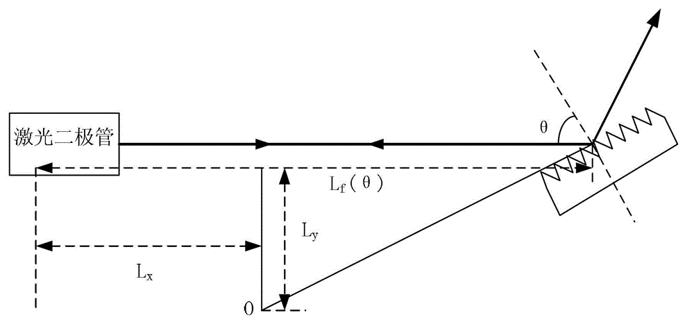
Technical field [0001] The invention relates to a Littrow structure tunable external cavity laser and a mode-hop-free frequency sweeping adjustment method thereof, belonging to the technical field of laser tuning. Background technique [0002] The Littrow structure external cavity laser can realize single-mode continuous frequency sweep, and its frequency adjustment is realized by rotating the grating. When an optimal grating rotation axis point is found, the laser can be continuously adjusted without mode-hopping frequency sweep. Its structure diagram such as figure 2 Shown. [0003] figure 2 In the process of tuning the laser, the grating rotates around point O. At this time, formula (1) and formula (2) jointly determine the wavelength λ of the laser beam emitted by the external cavity laser: [0004] λ r =d2sinθ, (1) [0005] λ q = 2 L f ( θ ) q , - - - ( 2 ) [0006] In the above formula, the wavelength λ of the laser beam emitt...

Claims


Application Information

Patent Timeline
IPC IPC(8): H01S5/14H01S5/06
Inventor 刘国栋路程甘雨陈凤东刘炳国庄志涛
Owner HARBIN INST OF TECH
Why Eureka
Try Eureka