A mems driver based on protruding comb teeth and its working method

A driver and comb-tooth technology, applied in the field of micro-electromechanical, can solve problems such as long-term use of unfavorable lasers and limit the application of lasers, and achieve the effect of facilitating manufacturing and reducing driving voltage

Active Publication Date: 2020-06-26
SHANDONG UNIV
View PDF5 Cites 0 Cited by
  • Summary
  • Abstract
  • Description
  • Claims
  • Application Information

AI Technical Summary

Problems solved by technology

[0004] In 2003, the external cavity tunable laser proposed by Ionon company used the design of the vertical MEMS mirror with in-plane movement to rotate around the imaginary axis point, which can realize wide-range mode-hop-free tuning, narrow linewidth, and high tuning speed, but In order to meet the wide range of mode-hop-free tuning, this design requires high voltage to drive the MEMS rotating mirror, which puts high requirements on the external drive circuit, which limits the application of the laser and is not conducive to the long-term use of the laser.

Method used


Image

  • A mems driver based on protruding comb teeth and its working method
  • A mems driver based on protruding comb teeth and its working method
  • A mems driver based on protruding comb teeth and its working method

Examples


Embodiment 1

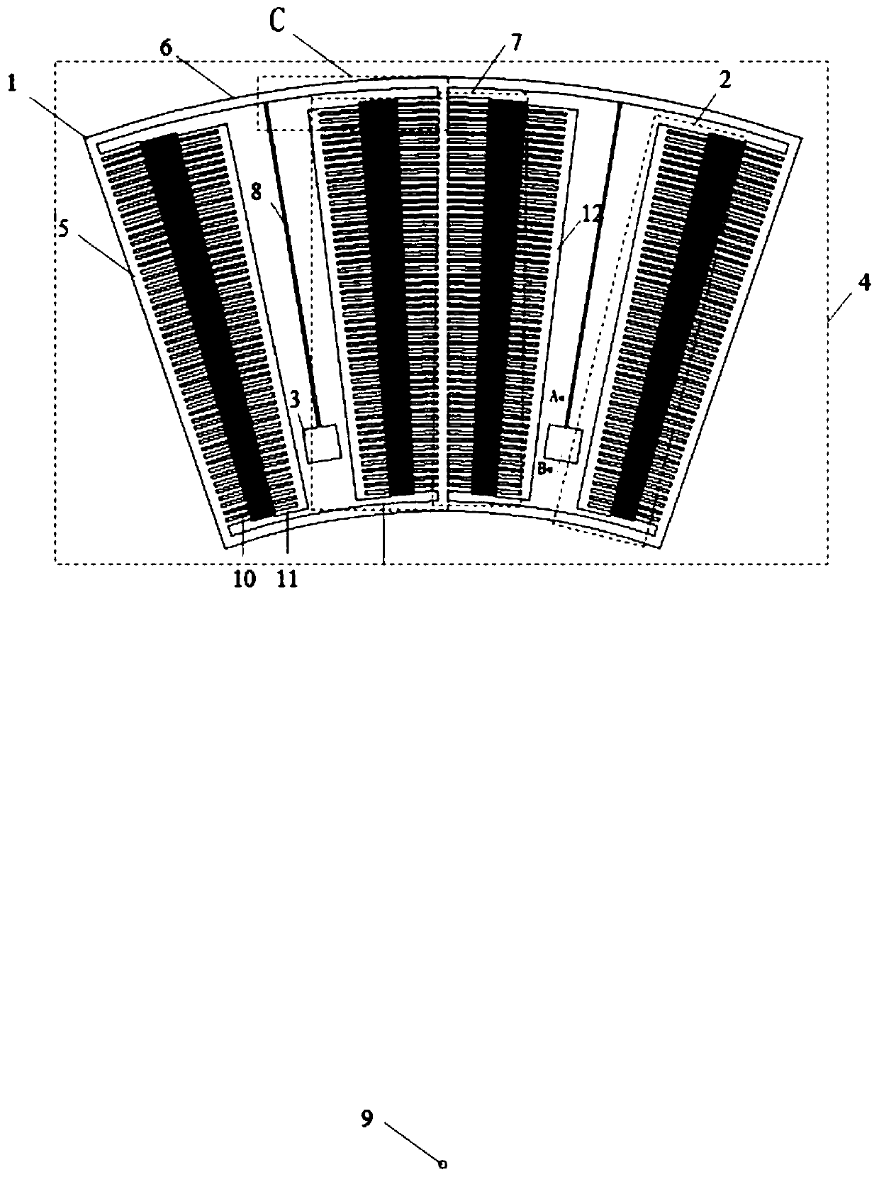
[0043] A MEMS actuator based on protruding comb teeth, such as Figure 1~5 As shown, it includes a movable part 1, a fixed comb 2, a fixed anchor point 3 and a base layer 4, and the fixed comb 2 and the fixed anchor point 3 are fixed on the base layer 4;

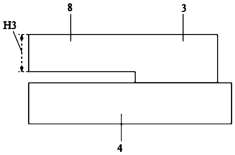
[0044] The movable part 1 includes a radial truss 5 , an arc truss 6 , a movable comb 7 and an elastic beam 8 , the arc truss 6 is arranged on the arc position with the imaginary axis point 9 as a circle, and the radial truss 5 is arranged along the radial direction, and the movable comb 7 includes a plurality of movable comb teeth 10, and the movable comb teeth 10 are connected by the radial truss 5 to form the movable comb 7, and the radial truss 5 and the arc truss 6 Connect at the intersection point, the fixed end of the elastic beam 8 is connected with the fixed anchor point 3, the connection method is as follows image 3 As shown, the free end of the elastic beam 8 is connected to the radial truss 5, and the elastic b...

Embodiment 2

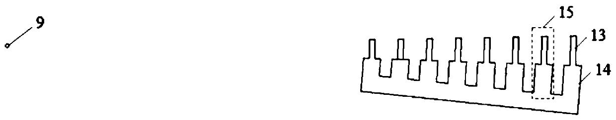
[0048] A MEMS driver based on protruding comb teeth, the structure is as shown in embodiment 1, the difference is that all front narrow comb teeth 13 have the same degree corresponding to the central angle of 2 °, and the width of all front narrow comb teeth 13 is It is equal to the central angle multiplied by the corresponding radius, and its width is 5um;

[0049] The center angles corresponding to all the rear-end wide comb teeth 14 are the same, which is 2.5°. The width of the rear-end wide comb teeth 14=central angle*corresponding radius, and the width is 13um.

Embodiment 3

[0051] A MEMS driver based on protruding comb teeth, the structure is as shown in embodiment 1, the difference is that the distance between the two adjacent rear end wide comb teeth 14 of the movable comb teeth 10, and the adjacent two rear end wide comb teeth 14 of the fixed comb teeth 11 The distance between the wide comb teeth 14 at the rear end is 9um.

[0052] When no voltage is applied, the distance H1 between the front narrow comb teeth 13 of the movable comb teeth 10 and the front narrow comb teeth 13 of the fixed comb teeth 11 is 6um to 8um, such as Figure 4 shown. After the voltage is applied, that is, after the front narrow comb teeth are inserted into the rear wide comb teeth, the spacing H2 is preferably 2um, such as Figure 5 As shown, the process requirements are relatively low.


PUM


Abstract

The invention relates to a MEMS actuator based on extruded comb teeth and a working method thereof, and belongs to the field of micro-electro-mechanical system, MEMS actuator comprises a movable part,fixed combs, fixed anchor points and a basal layer. The movable part comprises radical trusses, arc trusses, movable combs and elastic beams, the fixed combs and the movable combs are distributed inan intersecting mode in pairs, and movable comb teeth and fixed comb teeth are all protruded comb teeth. According to the MEMS actuator based on the extruded comb teeth and the working method thereof,compared with the prior art, a protruded comb tooth structure is adopted, the front-rear width of the comb teeth is different, after voltage is applied, the comb teeth with narrow front ends are inserted into the space distances slightly wider than the comb teeth, and the space distances between the comb teeth are smaller; different static electricity actuators are correspondingly formed at the front ends and the rear ends of the comb teeth, namely in the same structural length, more comb teeth can be arranged and used for driving, all of the comb teeth facilitate to decrease the voltage, theMEMS actuator can be apply to an external cavity tunable laser device, an optical grating or a plane mirror can be installed on the MEMS actuator, or the side surface of the MEMS actuator can be madeinto the optical grating or the plane mirror, and no-mode-skip tuning of the laser machine is realized.

Description

technical field [0001] The invention relates to a MEMS device structure, in particular to a protruding comb-based MEMS driver and a working method thereof, which belong to the field of micro-electromechanical technology. Background technique [0002] Since the advent of lasers, tunable light sources have received great attention. Compared with other lasers, tunable lasers have outstanding advantages such as compact structure, large tuning range, narrow line width, large-scale production, and low price, and have shown more and more extensive application prospects in the scientific field. It has many applications in spectral analysis, laser ranging, industrial field process detection, atmospheric environmental pollution detection, medical diagnosis, optical communication and radar. The common tunable lasers on the market can be roughly divided into distributed Bragg reflective lasers, distributed feedback laser arrays, highly integrated distributed feedback laser arrays, and ...

Claims


Application Information

Patent Timeline
Patent Type & Authority Patents(China)
IPC IPC(8): G02B26/08B81B5/00
CPCB81B5/00G02B26/0833G02B26/0841
Inventor 刘兆军李文睿秦增光关晨丛振华张行愚
Owner SHANDONG UNIV
Why Eureka
Try Eureka