Multi-body motor

A stator core and rotor core technology, applied in the field of multi-body motors, can solve the problems that the motor speed cannot be adjusted quickly and conveniently, and achieve the effect of completely consistent power supply time, not easy to vibrate, and low electromagnetic noise

Inactive Publication Date: 2013-06-12
胡风华 +1
View PDF7 Cites 5 Cited by
  • Summary
  • Abstract
  • Description
  • Claims
  • Application Information

AI Technical Summary

Problems solved by technology

Moreover, the motor cannot realize fast and convenient adjustment of the motor speed

Method used


Image

  • Multi-body motor
  • Multi-body motor
  • Multi-body motor

Examples


Embodiment 1

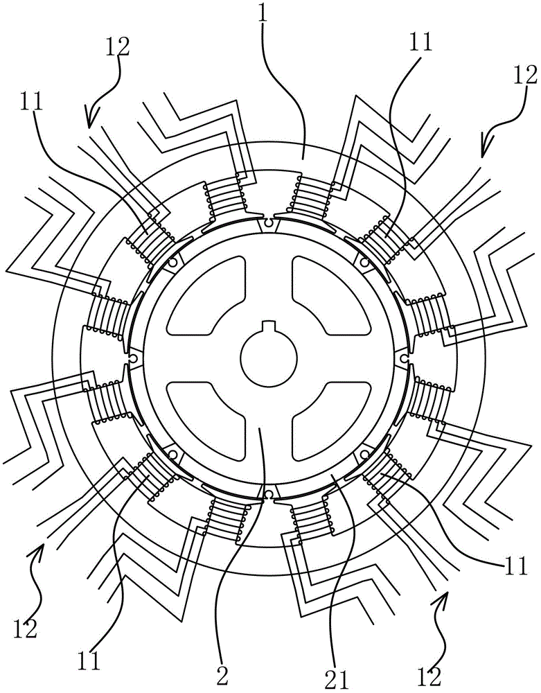
[0034] The multi-piece motor is a new motor structure which is different from the working mode of the existing motors. Among them, the multiple refers to the quantity, that is, to form a motor as a whole with multiple units that can work independently, and to use one or more units to work, so that a motor has different output power, which is equivalent to multiple motors driving the machine together. equipment. The multi-piece motor includes a stator core 1 , a rotor core 2 and an independent stator winding 12 .

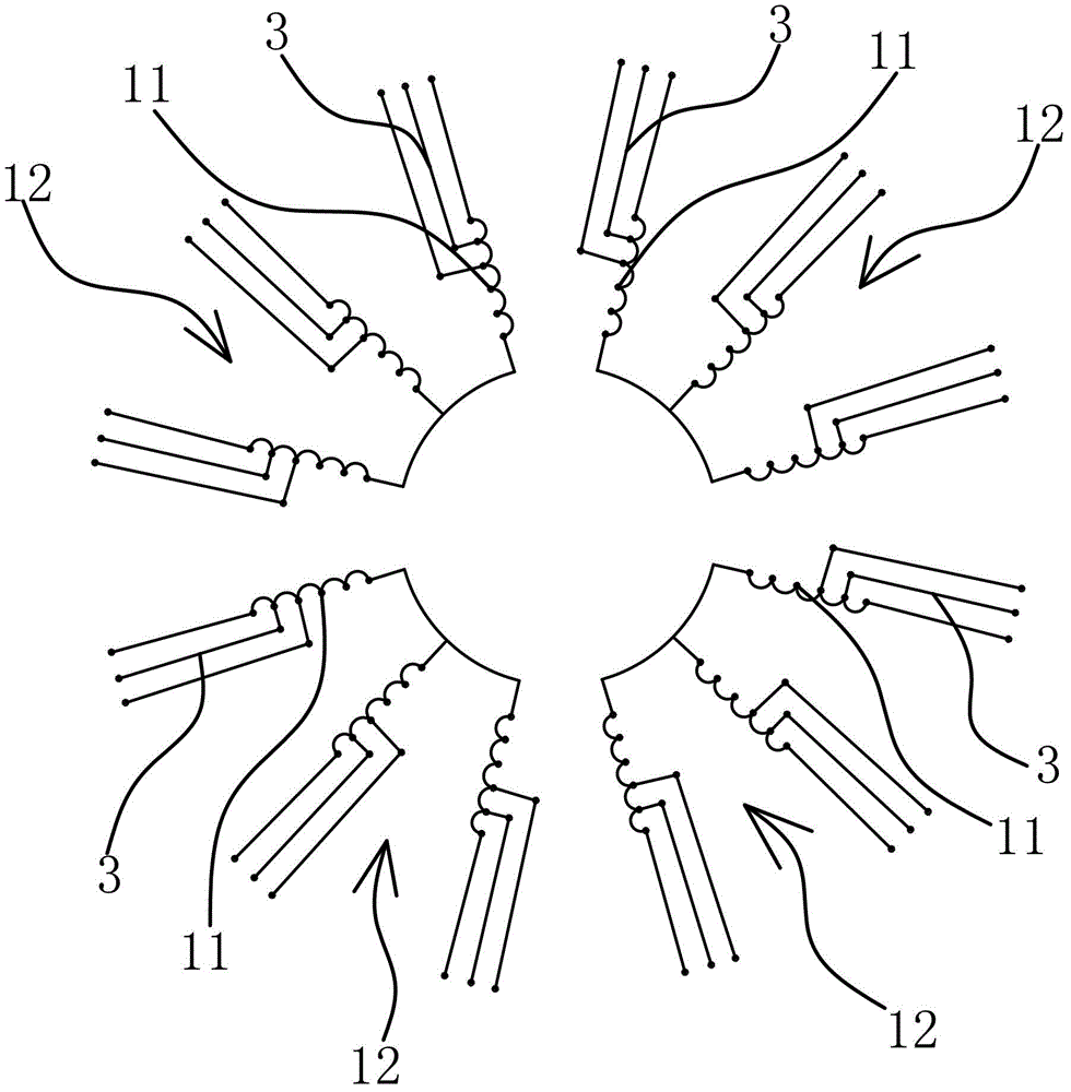
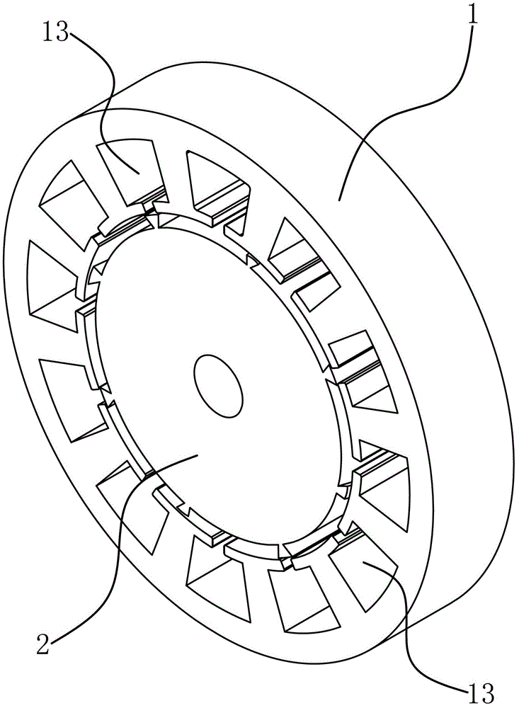
[0035] Specifically, as image 3 As shown, the cross section of the stator core 1 is circular, the rotor core 2 is located in the inner circle of the stator core 1 and can rotate relative to the stator core 1 , and the outer peripheral surface of the rotor core 2 is embedded with a magnetic steel sheet 21 . Several coils 11 are evenly arranged on the inner ring of the stator core 1 along the circumferential direction. At least three adjacent coils 11 form an indep...

Embodiment 2

[0039] The technical solution in this embodiment is basically the same as the technical solution in Embodiment 1, the difference is that in this embodiment, such as Figure 8 As shown, the number of stator windings 12 is six, the number of coils 11 is eighteen, and the number of magnetic steel sheets 21 is twelve.

Embodiment 3

[0041] The technical solution in this embodiment is basically the same as the technical solution in Embodiment 1, the difference is that in this embodiment, such as Figure 9 As shown, the multi-piece motor has an outer rotor structure, the rotor core 2 is located on the outer ring of the stator core 1, the inner peripheral surface of the rotor core is fixed with magnetic steel sheets, and the stator core 1 has the same number of coils as the coils 11. Slots 13 , the openings of the core slots 13 face outward, the coils 11 are embedded in the corresponding iron core slots 13 , and the magnetic steel sheets 21 are glued to the inner peripheral surface of the rotor core 2 . The working principle of this multi-piece motor is similar to that of the inner rotor motor, that is, the wiring of each stator winding 12 is independent of each other, and can work independently or simultaneously according to the needs of the use, realizing the multi-level power switching of the motor, which ...


PUM


Abstract

The invention provides a multi-body motor, and belongs to the technical field of motors, which solves the problem of the existing motor that the rotation speed cannot be quickly and conveniently adjusted. The multi-body motor comprises a stator iron core and a rotor iron core, wherein the cross section of the stator iron core is in an annular shape, the rotor iron core is positioned in an inner ring of the stator iron core and can rotate relative to the stator iron core, the peripheral surface of the rotor iron core is embedded with a magnetic steel sheet, the inner ring of the stator iron core is uniformly provided with a plurality of coils in the circumferential direction, at least three adjacent coils form an independent stator winding, the number of the independent stator windings is at least two, and each stator winding can independently form a rotary magnetic field after being energized. The multi-body motor has the advantages that the multiple independent stator windings are adopted, and when one part of stator windings works, the stator windings not working are not energized, so the stator windings not working have no empty load loss, the energy saving effect is good, and the switching of multiple rotation speed working conditions is convenient; and the electromagnetic noise in the whole working process of the motor is low, and the benefit is high.

Description

technical field [0001] The invention belongs to the technical field of motors, and relates to a multi-piece motor. Background technique [0002] In modern society, motor, as an important device that can convert electrical energy into mechanical energy, is widely used in industrial and agricultural production and people's daily life. Existing motors usually only have a fixed output power, and all coils are energized when the motor is working. [0003] For example, the Chinese patent [Patent No. ZL200920036999.X; Authorized Notice No. CN201365146Y] is a permanent magnet motor in which the permanent magnet is embedded in the stator and the rotor is a salient pole. The permanent magnet is embedded in the stator of the motor, and the armature winding is a concentrated winding. , each stator pole sleeve has a coil, and the two sides of the coil are respectively located in the stator slots on both sides of the stator pole, and each stator slot has two sides of the coil, and the nu...

Claims


Application Information

Patent Timeline
Patent Type & Authority Applications(China)
IPC IPC(8): H02K1/14H02K1/16H02K3/04H02K1/27
Inventor 章征凯
Owner 胡风华
Why Eureka
Try Eureka