Actuator, robot hand, robot, electronic component carrying device, and printer

A technology of actuators and piezoelectric elements, applied in the direction of robots, piezoelectric devices/electrostrictive devices, manipulators, etc., can solve the problems of loss of driving energy of the driving body, vibration leakage, driving energy loss of the driven body, etc.

Inactive Publication Date: 2013-06-12
SEIKO EPSON CORP
View PDF8 Cites 14 Cited by
  • Summary
  • Abstract
  • Description
  • Claims
  • Application Information

AI Technical Summary

Problems solved by technology

[0007] However, in the above-mentioned Patent Documents 1 and 2, the elastic member holding the piezoelectric body is arranged so as to restrict the vibration direction of the piezoelectric body, especially the vibration with respect to the bending vibration, which may cause the piezoelectric body to be damaged. The vibration leaks to the holding case through the elastic member, and a large amount of driving energy of the driven body is lost
In addition, in Patent Document 3, the piezoelectric body may also cause vibration leakage from the guide portion of the holding case, resulting in a large loss of driving energy of the driven body.

Method used


Image

  • Actuator, robot hand, robot, electronic component carrying device, and printer
  • Actuator, robot hand, robot, electronic component carrying device, and printer
  • Actuator, robot hand, robot, electronic component carrying device, and printer

Examples


no. 1 approach )

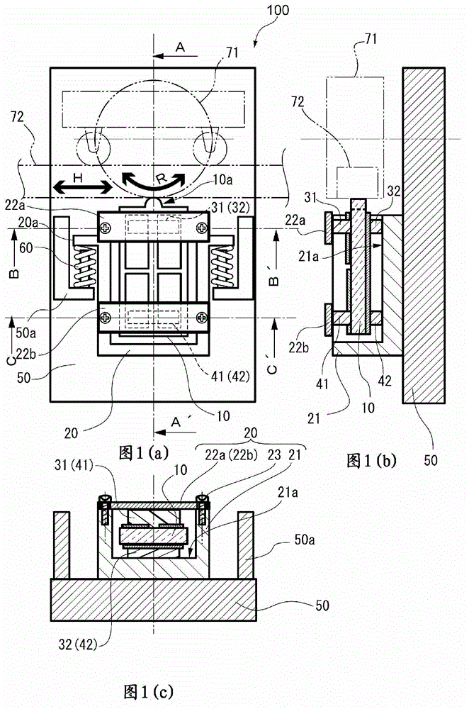
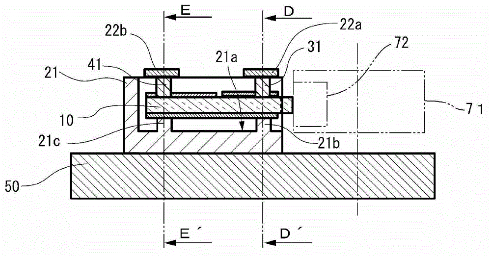
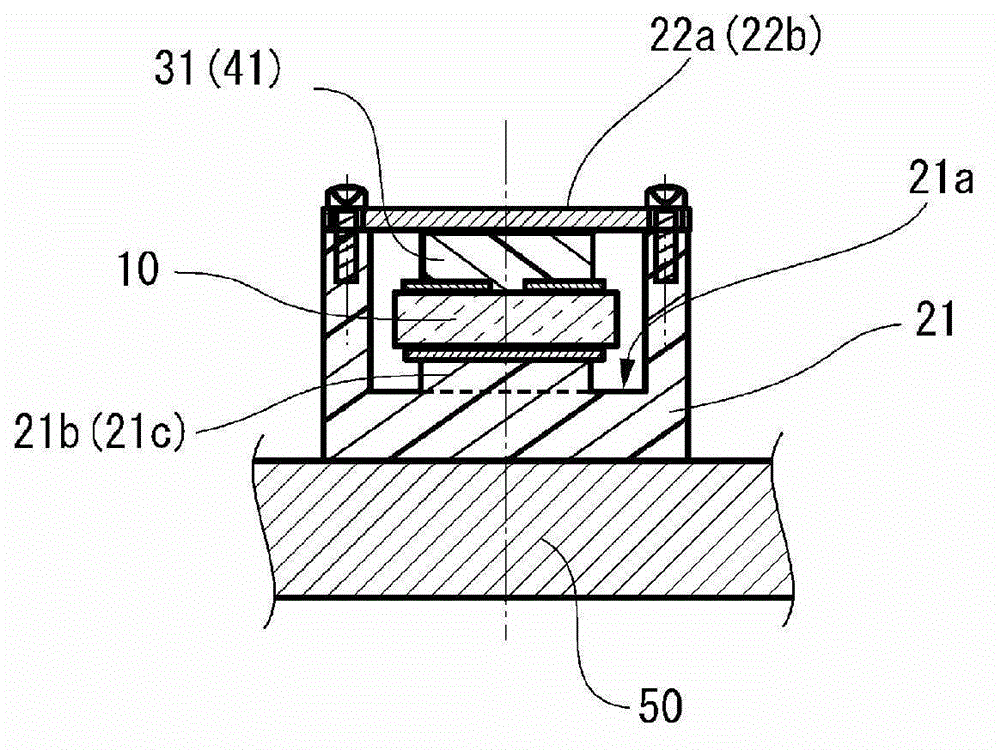
[0054] Fig. 1 shows the actuator of the first embodiment, Fig. 1(a) is a plan view, Fig. 1(b) is a cross-sectional view of the A-A' part shown in Fig. 1(a), Fig. 1(c) is Fig. 1(a) ) Sectional views of B-B' and C-C' parts. As shown in FIG. 1( a ), the actuator 100 includes a holding case 20 as a holding member, a piezoelectric element 10 held by the holding case 20 , and a spring serving as a biasing mechanism for the holding case 20 The base 50 and the driven body 71 or the driven body 72 of the spring fixing part 50a installed at 60.

[0055] The driven body 71 is driven to rotate in the illustrated R direction, and the driven body 72 is linearly driven in the illustrated H direction. In the actuator 100 according to the present embodiment, linear driving of the driven body 72 in the illustrated H direction is described, but the driven body 71 which is rotationally driven may also be described. The biasing portion 20 a of the holding case 20 is biased by the spring 60 relat...

no. 2 approach )

[0080] FIG. 9 is a schematic cross-sectional view of a portion B-B' and a portion C-C' indicated in FIG. 1( a ) of the support portion of the actuator according to the second embodiment. In addition, the actuator according to the second embodiment is different from the actuator 100 according to the first embodiment in that the supporting parts 31, 32, 41, 42 include elastic members, and the other structures are the same. Therefore, the same structures as those of the actuator 100 according to the first embodiment are denoted by the same reference numerals and description thereof will be omitted.

[0081] The actuator 300 shown in FIG. 9( a ) includes: a disc spring 91 serving as an elastic member in the first support portion 31 and the second support portion 41 , and a buffer member 81 . The disc spring 91 sandwiches the piezoelectric element 10 between the third support portion 32 and the fourth support portion 42 and the buffer member 81 and is disposed between the pressing ...

no. 3 approach )

[0087] Figure 10 It is an external view showing a robot hand 1000 including the actuator 100 or 300 according to the first embodiment. Figure 10 The actuator 100 included in the shown robot hand 1000 is the actuator 100 according to the first embodiment, and is in the form of a driven body 71 (see FIG. 1000 rotation drive motors for the joints are used. The robot hand 1000 includes fingers 1200 connected to a base 1100 . The actuator 100 as a rotation drive motor is provided at the connection part 1300 of the base part 1100 and the finger part 1200 and the joint part 1400 of the finger part 1200 . In addition, a control unit 1500 is provided on the robot hand 1000, and the actuator 100 is driven by the control unit 1500, so that the connection unit 1300 and the joint unit 1400 can be rotated, and the fingers 1200 can be deformed as desired like a human finger. status.


PUM


Abstract

The invention provides an actuator, a robot hand, a robot, an electronic component carrying device, and a printer. The actuator includes a vibrating piezoelectric element, and a holding unit that holds the piezoelectric element, in which the holding unit is disposed on a vibrating surface of the piezoelectric element, and includes a first support unit and a second support unit that are disposed on one side of the piezoelectric element, and a third support unit and a fourth support unit that are disposed on the other side of the piezoelectric element.

Description

[0001] technology area [0002] The present invention relates to an actuator, a robot arm, a robot, an electronic component conveying device, an electronic component inspection device and a printer. Background technique [0003] As a conventional driving method of an actuator, it is known to vibrate a piezoelectric body in two vibration modes, make the protrusion provided at the end of the piezoelectric body form an elliptical orbit, and drive the actuator in contact with the protrusion. A method of driving the part in a specified direction. In this actuator, in order to urge the piezoelectric body toward the driven part, the side surface side of the vibration surface of the piezoelectric body is pressed and held via the elastic member in the holding case, and is driven toward the driven part by the urging mechanism. A force is applied to the holding case in the direction of the body, and a force is applied to the piezoelectric body toward the driven body (Patent Documents 1 ...

Claims


Application Information

Patent Timeline
Patent Type & Authority Applications(China)
IPC IPC(8): H02N2/00B25J9/00H01L41/09
CPCB41J19/20H02N2/0015H02N2/004H02N2/006H02N2/026H02N2/103B25J15/0009H02N2/0055Y10S901/32H02N2/04B25J15/00B25J15/024H10N30/88H10N30/204H02N2/028H02N2/108
Inventor 上条浩一水岛信幸宫泽修
Owner SEIKO EPSON CORP
Why Eureka
Try Eureka