Quick switching device for valve

A fast switching and valve technology, applied in valve devices, valve operation/release devices, valve details, etc., can solve problems such as oil leakage accidents in hydraulic systems, damage to hydraulic components, vibration damage to hydraulic pipelines and joints, etc. The effect of safety, investment and maintenance cost reduction

Active Publication Date: 2012-03-21
SHIJIAZHUANG SHITE VALVE
View PDF6 Cites 8 Cited by
  • Summary
  • Abstract
  • Description
  • Claims
  • Application Information

AI Technical Summary

Problems solved by technology

Since bypass quick-opening butterfly valves are mostly driven by hydraulic servo cylinders, it is easy to cause vibration damage to hydraulic pipelines and joints, damage to hydraulic components, and oil leakage accidents in the hydraulic system during use.

Method used


Image

  • Quick switching device for valve
  • Quick switching device for valve
  • Quick switching device for valve

Examples


Embodiment Construction

[0015] Below in conjunction with accompanying drawing, the present invention is described in further detail:

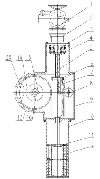
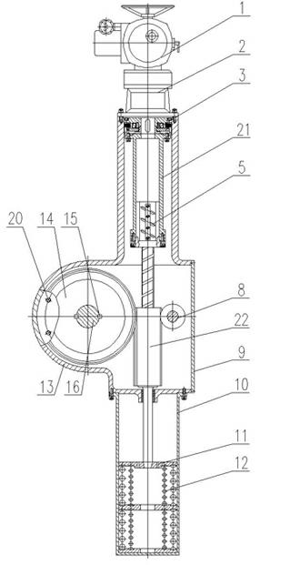
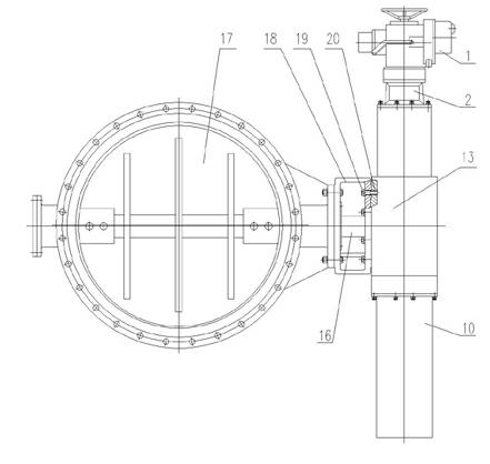
[0016] like figure 1 As shown, the valve quick switching device of the embodiment of the present invention includes a multi-turn electric device 1, a cycloidal pinwheel reducer 2 connected to the multi-turn electric device 1, an electromagnetic clutch 3 connected to the output end of the cycloidal pinwheel reducer 2, The ball screw pair 5 connected with the driven end of the electromagnetic clutch 3 through the connecting screw 4, the hollow push rod rack 7 connected with the nut of the ball screw pair 5 through the connecting screw 6, and the gear meshed with the hollow push rod rack 7 14. The spring seat 11 and the combined spring 12 that are in contact with the push rod end of the hollow push rod rack 7, and the hollow push rod rack 7 is equipped with a limit device 8 that ensures the linear movement of the hollow push rod rack; The electromagnetic clutch 3, the b...


PUM


Abstract

The invention provides a quick switching device for a valve, which comprises a multi-turn electric device, a cycloidal pin wheel speed reducer, an electromagnetic clutch, a ball screw assembly, a hollow push rod rack, a gear, a spring seat and a combined spring, wherein the hollow push rod rack is provided with a limit device in a matching way; the electromagnetic clutch, the ball screw assembly,the hollow push rod rack, the limit device and the gear are arranged in a gearbox body in a sealing way; the upper connector end of the gearbox body is fixedly connected with the cycloidal pin wheel speed reducer; a connecting hole is formed on the gearbox body; the spring seat and the combined spring are arranged in a spring drum; the spring drum is fixedly connected with the lower connector endof the gearbox body; the centers of the two connector ends of the gearbox body are on the same line; and the symmetrical center of the connecting hole on the gearbox body and the center of the gear are on the same line. The quick switching device avoids the damage and oil leakage of pressure pipe fittings, reduces the investment and maintenance cost and is more reliable and safer to use.

Description

technical field [0001] The invention relates to a valve quick switching device, in particular to a device for gas pipelines in the metallurgical industry, which drives a partial rotation of a valve to realize quick opening or closing. Background technique [0002] At present, the bypass pipeline of the blast furnace gas residual pressure turbine power generation device is equipped with a hydraulic quick-opening butterfly valve. The gas flows through the bypass pipe to ensure the safe operation of the gas system. Since bypass quick-opening butterfly valves are mostly driven by hydraulic servo cylinders, it is easy to cause vibration damage to hydraulic pipelines and joints, damage to hydraulic components, and oil leakage accidents in the hydraulic system during use. Contents of the invention [0003] The purpose of the present invention is to provide a valve quick switching device, which overcomes the shortcomings of the traditional valve hydraulic drive device servo cylin...

Claims


Application Information

Patent Timeline
Patent Type & Authority Applications(China)
IPC IPC(8): F16K31/04F16K31/72F16K31/50F16K31/54
Inventor 姜亚平李建红李月英
Owner SHIJIAZHUANG SHITE VALVE
Why Eureka
Try Eureka